Antenna and antenna arrangement for magnetic resonance applications

a technology of magnetic resonance and antenna, applied in the field of mri or mr spectroscopy, can solve the problems of inability to adjust the tuning behavior of the antenna at higher frequencies, the adverse effect of the hf /sub>field on the production and tuning of the antenna, and the inability to manufacture the antenna. the effect of facilitating the manufacture of the antenna and adjusting the secondary shielding conductor

Inactive Publication Date: 2014-07-17
MAX PLANCK GESELLSCHAFT ZUR FOERDERUNG DER WISSENSCHAFTEN EV
View PDF9 Cites 80 Cited by
  • Summary
  • Abstract
  • Description
  • Claims
  • Application Information

AI Technical Summary

Benefits of technology

[0036]According to a modified variant, the conductor loop can form at least two rings and / or polygons, which form one single resonant circuit and extend in a common plane or can be arranged inclined relative to each other, e.g. perpendicularly or at another angle. If the rings and / or polygons are separately excitable and form a plurality of resonant circuits, an antenna arrangement is created (see below).
[0037]According to further modified variants, the conductor loop can have a crossing or intersection of the waveguide. For example, the conductor loop can have a form corresponding to the numeral eight. Advantages for forming the antenna characteristic can result with these variants.
[0038]According to a particularly preferred embodiment of the invention, the conductor loop comprises a coaxial cable, the ends of which form the feed points of the antenna. Advantageously, manufacturing the antenna is facilitated by using a flexible coaxial cable. The inner conductor of the coaxial cable forms the inner conductor of the antenna, while the outer conductor of the coaxial cable forms the primary shielding conductor. Preferably, the at least one gap in the primary shielding conductor is arranged symmetrically with respect to the feed points. The coaxial cable carries on the surface of the outer conductor, i.e. on the primary shielding conductor, an insulator layer, which provides the dielectric between the primary and secondary shielding conductors of the antenna according to the invention. The secondary shielding conductor is formed by an electrically conductive coating, e.g. made of a metal, such as copper, silver, gold or aluminum, or of a metal alloy, such as brass or German silver, or of a metal-graphite composite on the insulator layer.
[0039]The choice of the thickness and the type of the dielectric between the primary shielding conductor and the secondary shielding conductor and the overlapping area by the secondary shielding conductor influences the extension of the tuning range towards higher frequencies (in particular beyond the limit defined in conventional loop antennas by λ / 4). The length of the secondary shielding conductor can be selected freely in particular depending on the conditions in the production of the antenna and the setting of a desired resonant frequency of the antenna. According to a preferred embodiment of the invention, it is however provided that the secondary shielding conductor has in the circumferential direction of the conductor loop a length, which is at least the triple width of the covered gap.
[0040]Particularly preferably, adjustability of the secondary shielding conductor is provided for. In this variant, the length of the secondary shielding conductor in the circumferential direction of the conductor loop is variable. To this effect, the secondary shielding conductor can comprise, for example, two shielding conductor sections that are connected together electrically and can be shifted relative to each other. For example, the secondary shielding conductor may be formed by two sliding metal sleeves, wherein the length of the secondary shield conductor depends on the mutual position of the overlapped metal sleeves.
[0041]For the production and function of the antenna according to the invention, it has proved advantageous if the thickness of the dielectric between the primary and secondary shielding conductors is at least 10 μm, preferably at least 50 μm. Preferred materials for the dielectric are polyolefines such as, for example, polyethylene or polypropylene. In this case, advantages result for the production of the dielectric, for example by shrinking of a hose. Alternatively, polytetrafluoroethylene (PTFE) or phenolic resins or, with appropriate supporting of the secondary shielding conductor, an inert gas, air or vacuum can be used as the dielectric. According to a further alternative, the dielectric can comprise a metal oxide, such as e.g. aluminium oxide or titanium dioxide, a mineral, a ceramic or glass. Advantages for the production of the dielectric can result in this case from application of a metal oxide paste.

Problems solved by technology

With reference to the nuclear resonance, the EHF field has undesirable impacts.
Early efforts to reduce the unwanted EHF field to a value as low as possible (e.g. through a symmetrical excitation or the use of a so-called high current probe) have proved adverse at higher frequencies with respect to the production and the tuning and adaptation behavior of the antenna.
For the following reasons, conventional magnetic antennas have, however, the disadvantage that they cannot be tuned at higher frequencies with a capacitor and, therefore, their application is limited to the radio technology in the shortwave and VHF range.
The wavelength however decreases with increasing frequencies, so that above certain limits, a suitable constructive size of tunable antenna is no longer possible.
However, setting up and partly also the tuning are significantly more complicated.

Method used


Image

  • Antenna and antenna arrangement for magnetic resonance applications
  • Antenna and antenna arrangement for magnetic resonance applications
  • Antenna and antenna arrangement for magnetic resonance applications

Examples


Embodiment Construction

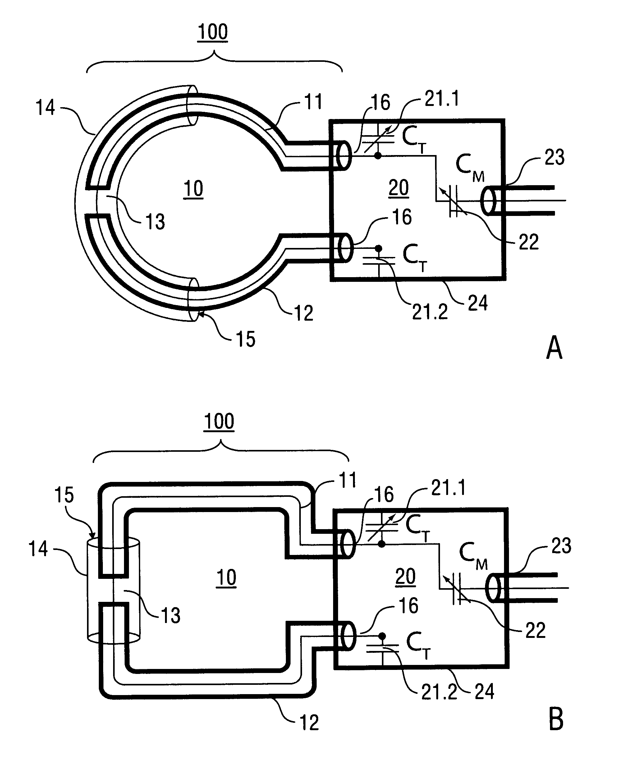
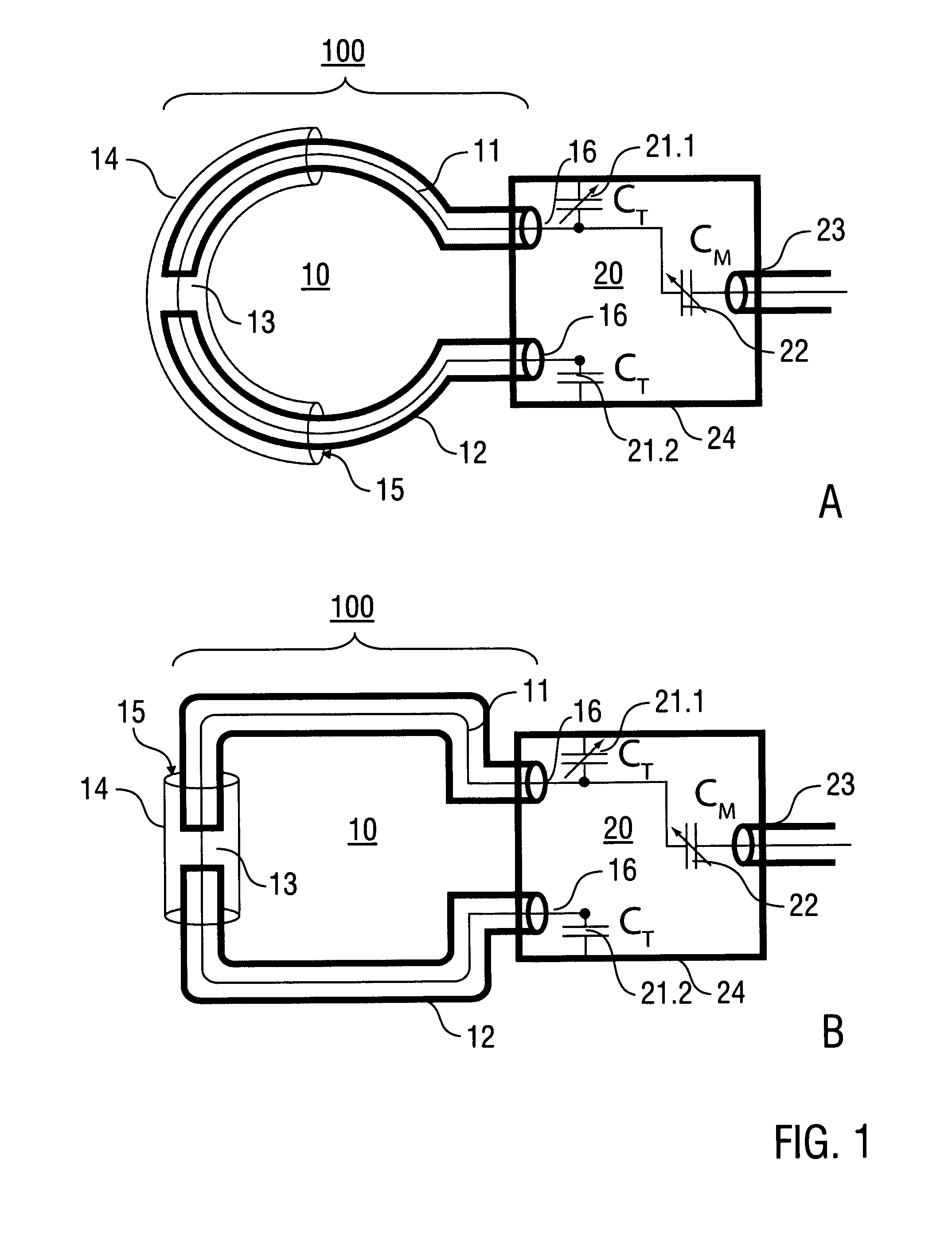
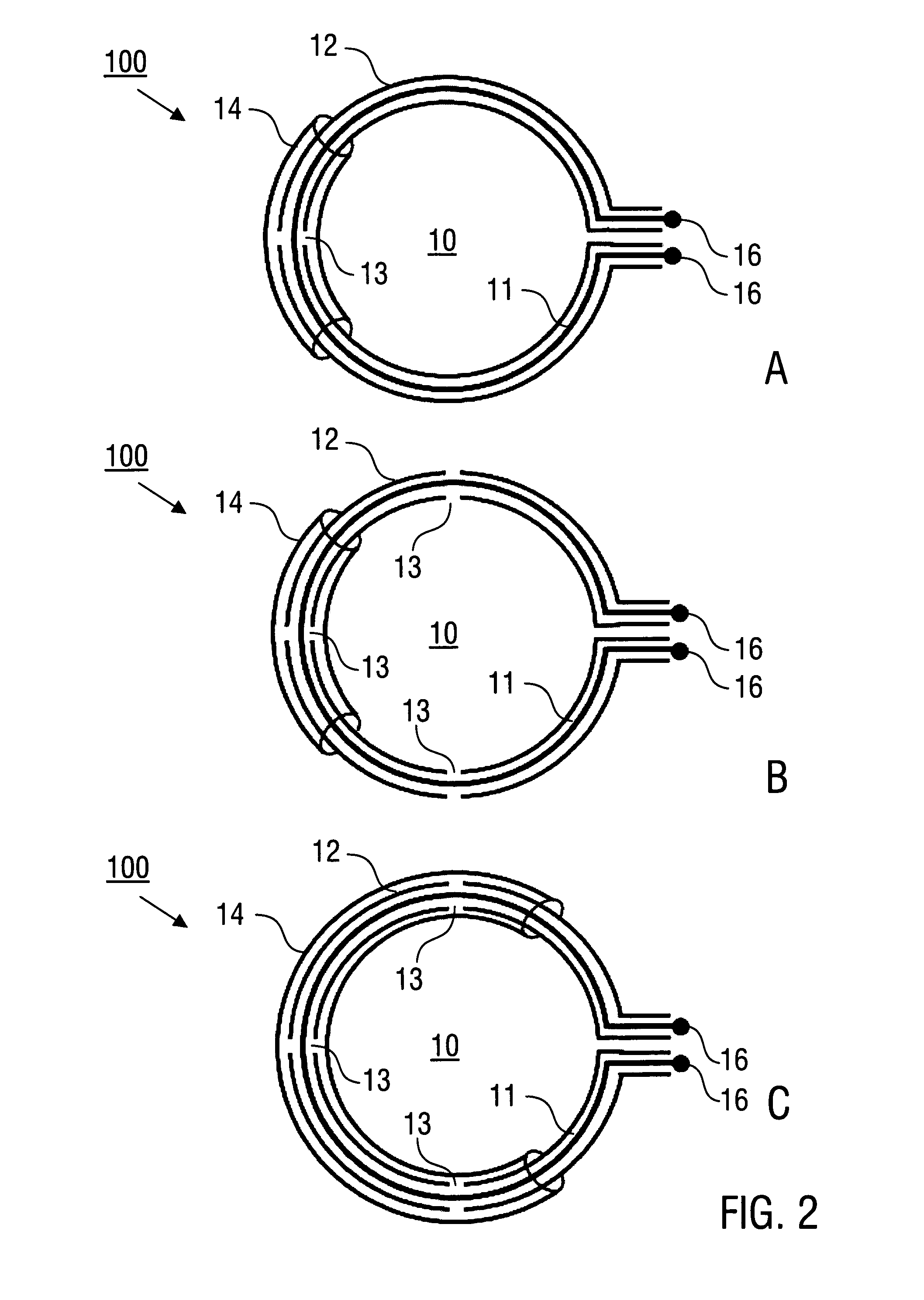
[0070]Embodiments of the invention are described in the following with exemplary reference to antennas, whose conductor loop comprises at least one loop made of a coaxial waveguide with at least one gap and an additional secondary shielding conductor over the at least one gap. The implementation of the invention is not restricted to the illustrated examples, but can be accomplished in a corresponding manner with loop arrangements which comprise differently formed loops and / or other forms of waveguides.

[0071]Furthermore, the invention is described hereinafter with reference by way of example to antennas, which extend along a planar reference surface (reference plane). Correspondingly, the invention can be implemented with curved reference surfaces. Although the feed points of the antenna are illustrated at the ends of the conductor loop, the feed points can alternatively be provided in other sections of the waveguide of an antenna.

[0072]Finally, it should be noted that the capacitanc...


PUM


Abstract

An antenna (100), which is designed for exciting and/or detecting a magnetic resonance in an object (1) under investigation, comprises a conductor loop (10) with an inner conductor (11) and a primary shield conductor (12), which form at least one waveguide, wherein the primary shield conductor (12) is interrupted by a gap (13), and wherein a secondary shield conductor (14) is provided which surrounds the primary shield conductor (12), wherein a dielectric (15) is arranged between the primary shield conductor (12) and the secondary shield conductor (14) and at least the gap is covered by the secondary shield conductor (14). An antenna arrangement which comprises a plurality of such antennas, a magnetic resonance device, and a method for magnetic resonance imaging or magnetic resonance spectroscopy are also described.

Description

[0001]The invention concerns an antenna, which is adapted for exciting and / or detecting a magnetic resonance (MR) in an object to be examined. The invention also relates to an antenna arrangement (antenna array) for an MR-device and to a method of operating the MR device and methods of operating of an MR device, in particular methods for magnetic resonance imaging or magnetic resonance spectroscopy. The invention can be used in particular in the magnetic resonance imaging (MR imaging; also magnetic resonance tomography, MRT, or magnetic resonance imaging, MRI) and in the magnetic resonance spectroscopy (MR spectroscopy).PRIOR ART[0002]In the following, reference is made to the publications listed below, for illustrating the prior art, in particular as regards the MRI or MR spectroscopy.[0003][1] D. I. Hoult. The NMR receiver: a description and analysis of design. Prog. NMR Spectr. 12: 41-77 (1978).[0004][2] H. J. Zabel, R. Bader, J. Gehring, W. J. Lorenz. High-quality MR imaging wit...

Claims


Application Information

Patent Timeline
Patent Type & Authority Applications(United States)
IPC IPC(8): G01R33/36
CPCG01R33/36H01Q7/005H01Q7/04G01R33/34007G01R33/3415G01R33/3628G01R33/422
Inventor DRIESEL, WOLFGANGMILDNER, TORALFSCHAEFER, ANDREASMOELLER, HARALD
Owner MAX PLANCK GESELLSCHAFT ZUR FOERDERUNG DER WISSENSCHAFTEN EV
Why Eureka
Try Eureka