Multi-spot laser probe with micro-structured distal surface

a laser probe and microstructure technology, applied in metal working devices, manufacturing tools, surgery, etc., can solve the problems of large number of additional, and large number of extraneous beam spots,

Inactive Publication Date: 2014-07-17
NOVARTIS AG
View PDF5 Cites 29 Cited by
  • Summary
  • Abstract
  • Description
  • Claims
  • Application Information

AI Technical Summary

Benefits of technology

[0008]Consistent with some embodiments, there is provided an optical surgical probe that includes a cylindrical cannula; a light guide within the cannula, configured to receive a light beam from the light source, to guide the light beam to a distal end of the light guide, and to emit the light beam at the distal end of the light guide; and a multi-spot generator at a distal end of the cannula, the multi-spot generator having a faceted proximal surface with oblique facets, configured to receive the light beam emitted at the distal end of the light guide and to split the received light beam into multiple beam-components, and a distal surface from which the multiple beam-components exit the multi-spot generator, wherein the distal surface is micro-structured with a modulation length smaller than a wavelength of the light beam.

Problems solved by technology

Difficulties, however, can arise with using diffractive elements at the distal end of the probe.
For example, diffractive elements can produce a multitude of higher diffraction orders and thus a large number of additional, unwanted, extraneous beam spots that will irradiate the retina.
These additional spots, in spite of having lower intensities, may have negative effects, such as undesirable heating of the target region.
Moreover, a diffractive element may not perform the same in different refractive media.
Furthermore, the spacing between the spots can vary for different wavelengths, which can cause problems if an aiming beam and a treatment beam are different colors.
Diffractive elements are also frequently expensive and difficult to produce, especially if the diffractive element is to fit into a small area.
However, both the proximal and the distal surfaces of the cured adhesive reflect as much as 5% of the incident light back into the laser probe, causing problems related to overheating such as material degradation of the adhesive.

Method used


Image

  • Multi-spot laser probe with micro-structured distal surface
  • Multi-spot laser probe with micro-structured distal surface
  • Multi-spot laser probe with micro-structured distal surface

Examples


Embodiment Construction

[0019]In the following description specific details are set forth describing certain embodiments. It will be apparent, however, to one skilled in the art that the disclosed embodiments may be practiced without some or all of these specific details. The specific embodiments presented are meant to be illustrative, but not limiting. One skilled in the art may realize other material that, although not specifically described herein, is within the scope and spirit of this disclosure.

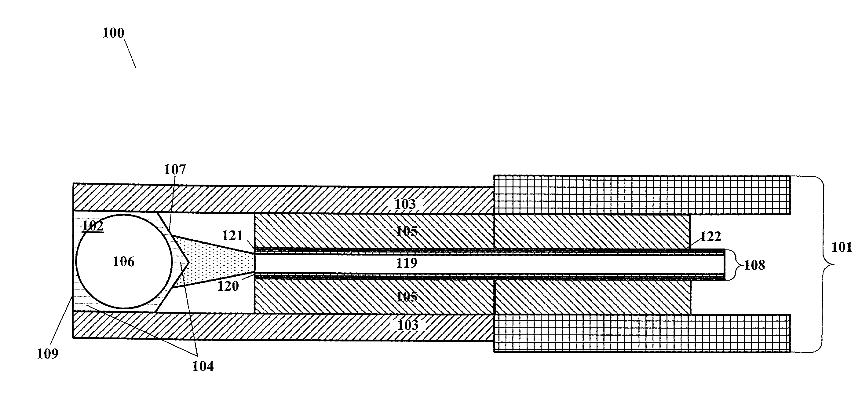
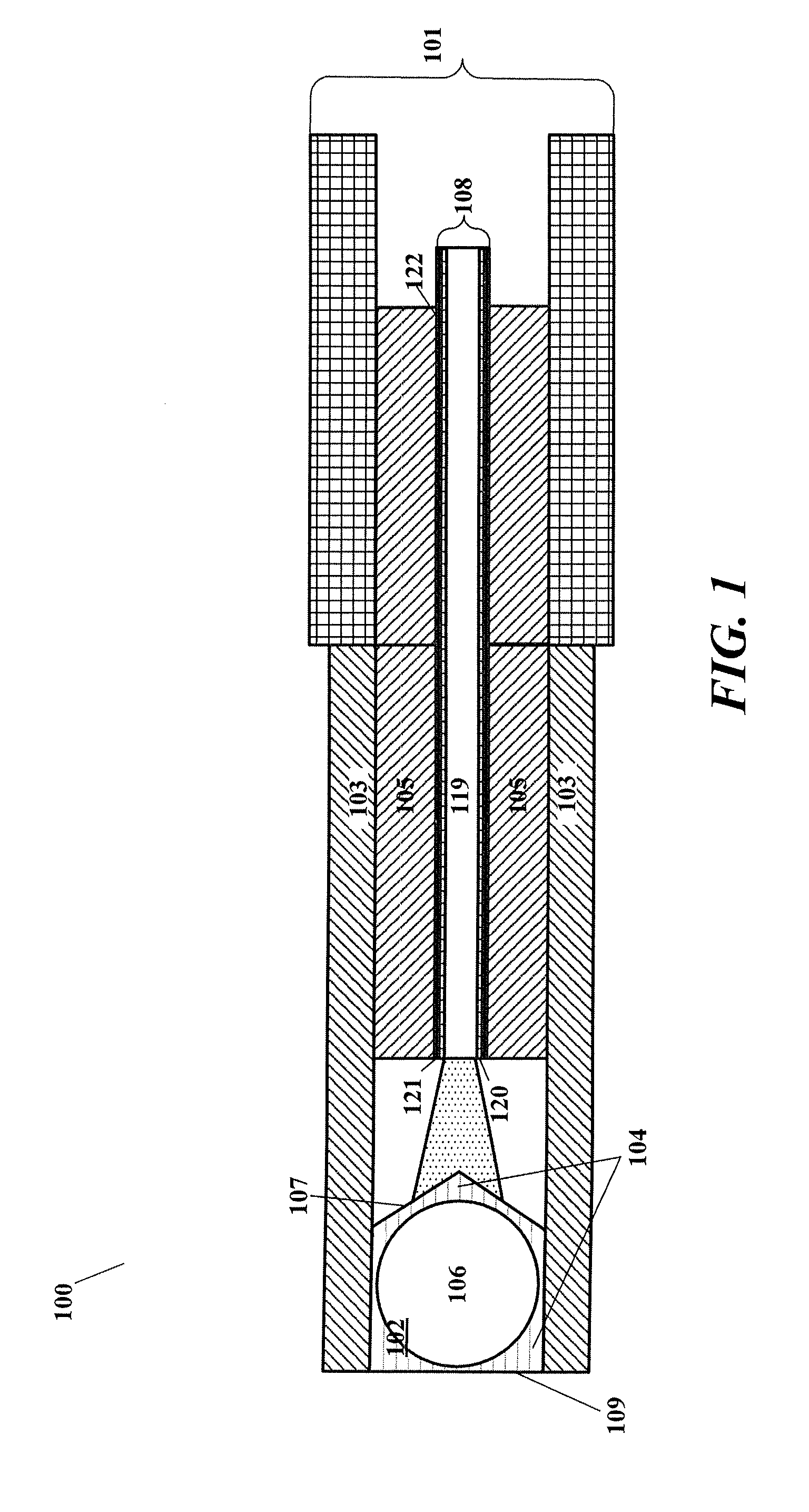
[0020]FIG. 1 illustrates an example of an optical surgical probe 100 that can include a cylindrical cannula 103, and a light guide 108 within the cannula, configured to receive a light beam from the light source, to guide the light beam to a distal end of the light guide 108, and to emit the light beam at the distal surface of the light guide 108. The light guide 108 can be an optical fiber, disposed within a stainless steel ferrule 105. The optical surgical probe 100 can further include a multi-spot generator...


PUM

PropertyMeasurementUnit
diameteraaaaaaaaaa
refractive indexaaaaaaaaaa
Fresnel reflectanceaaaaaaaaaa

Abstract

An optical surgical probe, configured to optically couple to a light source; comprising a cannula; a light guide within the cannula, configured to receive a light beam from the light source, to guide the light beam to a distal end of the light guide, and to emit the light beam at the distal end of the light guide; and a multi-spot generator at a distal end of the cannula, the multi-spot generator having a faceted proximal surface with oblique facets, configured to receive the light beam emitted at the distal end of the light guide and to split the received light beam into multiple beam-components, and a distal surface through which the multiple beam-components exit the multi-spot generator, wherein the distal surface is micro-structured with a modulation length smaller than a wavelength of the light beam in order to reduce the reflectance of light back into the probe.

Description

BACKGROUND[0001]1. Technical Field[0002]Embodiments disclosed herein are related to a multi-spot laser probe having a micro-structured distal surface and methods for manufacturing the same. In particular, some embodiments disclosed herein provide a multi-spot laser probe having a micro-structured distal surface and a faceted proximal surface and method for manufacturing the same that may reduce a total internal reflectance back into the laser probe.[0003]2. Related Art[0004]Laser probes may deliver light to multiple spots onto a surgical target. For example, in the course of pan-retinal photocoagulation of retinal tissue, delivering light to multiple spots can reduce the time of the surgical procedure. In existing system various techniques have been employed to produce multiple beams for a multi-spot pattern. For example, one approach uses diffractive elements at the distal end of the probe to divide an incoming beam into multiple beams.[0005]Difficulties, however, can arise with us...

Claims


Application Information

Patent Timeline
Patent Type & Authority Applications(United States)
IPC IPC(8): A61B18/20B23P11/00
CPCB23P11/00A61B18/201A61B18/22A61B2018/2272A61B2018/2266A61F9/00821A61F2009/00863Y10T29/4998
Inventor SMITH, RONALD T.
Owner NOVARTIS AG
Why Eureka
Try Eureka