
Auto-focus raman spectrometer system

a raman spectrometer and auto-focus technology, applied in the direction of instruments, spectrometry/spectrophotometry/monochromators, optical radiation measurement, etc., can solve the problems of operator dependence, relative complexity in structure, inefficient, etc., and achieve the effect of simple structur

Inactive Publication Date: 2016-03-31
YANG FR JIANN FU
View PDF0 Cites 20 Cited by
  • Summary
  • Abstract
  • Description
  • Claims
  • Application Information

AI Technical Summary

Benefits of technology

The present invention is an autofocus Raman spectrometer system that can automatically and accurately measure the Raman scattering of a sample. It includes a laser probe assembly, a microprocessor, an adjustable stage, and a driving means. The system can easily focus the laser beam onto the sample using the adjustable stage and driving means. The microprocessor analyzes the signals from the spectrographic detector and generates a command to the driving means to achieve optimal focusing. The technical effect of this invention is to provide a simple and automated way to measure the Raman spectrum of samples.

Problems solved by technology

As can be understood, the conventional system combines a microscope and a Raman spectrometer together, which makes it relatively complex in structure.
Thus, the Raman measurement becomes relatively time-consuming, inefficient, and operator dependent.

Method used


Image

  • Auto-focus raman spectrometer system
  • Auto-focus raman spectrometer system
  • Auto-focus raman spectrometer system

Examples


Embodiment Construction

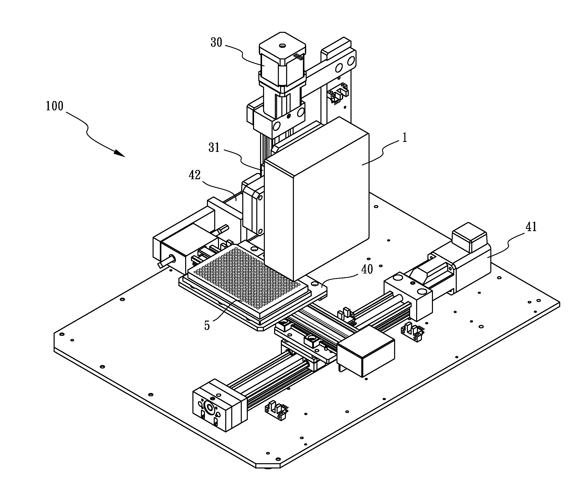
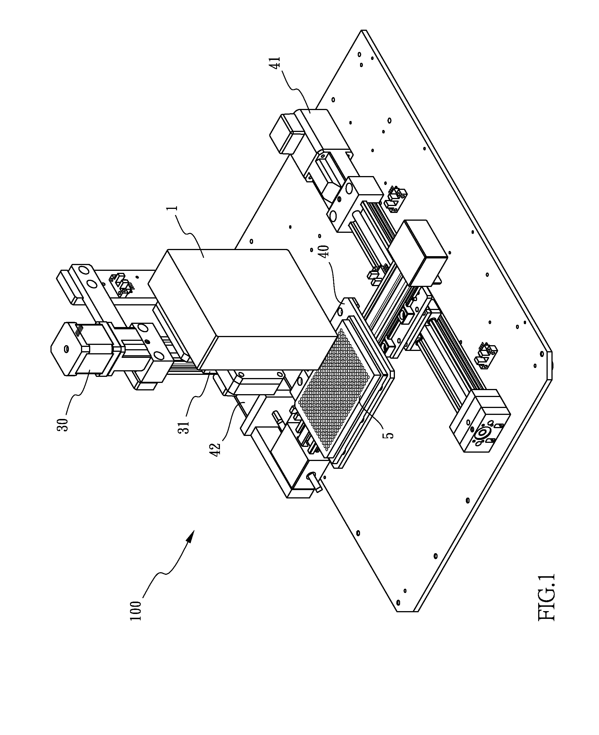
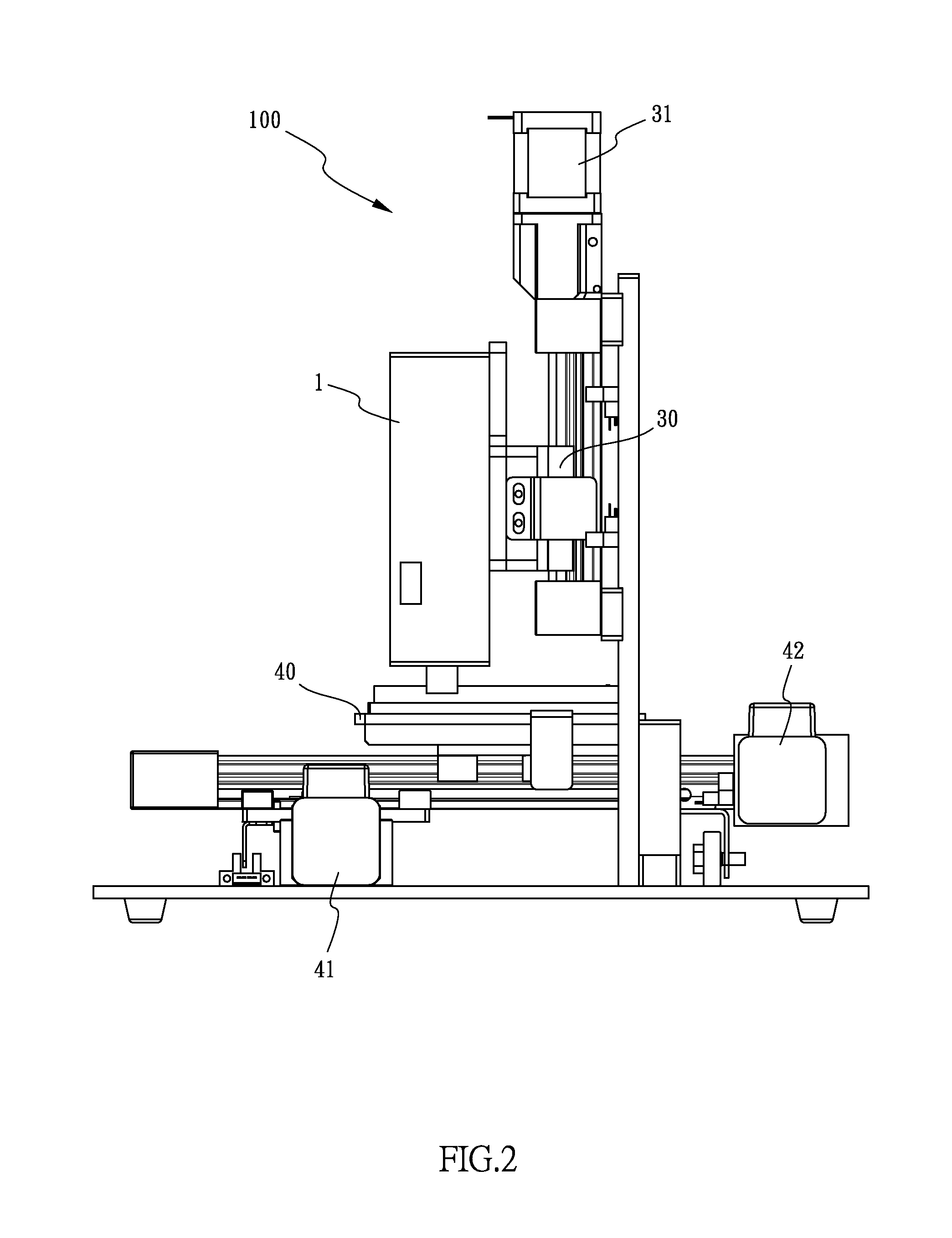
[0016]Referring now in detail to the drawing, there is shown a robotic controlled autofocus Raman spectrometer system for material identification and quantification, indicated generally at 100, which has been constructed according to the principles of the present invention.

[0017]With reference to FIGS. 1 and 2, the autofocus Raman spectrometer system 100 includes a laser probe assembly 1, a computer 2 (not depicted in FIGS. 1 and 2) connected to the laser probe assembly 1, a Z-axis motorized stage 30 on which the laser probe assembly 1 is situated, a Z-axis drive 31 provided for driving the stage 30 to move, a X-Y axis motorized stage 40 on which a sample or sample holder 5, and X-Y axis drives 41, 42, configured for driving the stage 40 to move horizontally. As such, the laser probe assembly 1 is movable with respect to the sample 5. The sample may be in the form of solid, powder, liquid, tablet, sheet, SERS, in vial, or in plastic bag.

[0018]Specifically, as best seen in FIG. 3, th...


PUM


Abstract

An autofocus Raman spectrometer system includes a laser probe assembly, a microprocessor, adjustable stages and a driving means. The laser probe assembly includes an excitation means, a focusing optics provided to focus an excitation beam from the excitation means onto a sample and generate Raman scattering spectrum, a collection optics for collecting the Raman scattering spectrum, and a spectrographic detector for generating a Raman spectrum based on the Raman scattering intensity received from the collection optics. The microprocessor receives the Raman spectra signal therefrom. The laser probe assembly is situated on the adjustable stage. The driving means is coupled to the microprocessor and configured to drive the stage to move with respect to the sample. The microprocessor generates a command to the driving means for moving a position of the adjustable stage to achieve an optimal optical focus based on signal intensity of the spectra peaks measured by the spectrographic detector.

Description

BACKGROUND OF THE INVENTION[0001]1. Field of the Invention[0002]The present invention relates to the field of Raman spectrometry instrumentation used for material identification and quantification. The instrument can be used to analyze solid, liquid, and gas. More particularly, the present invention relates to a Raman spectrometer system having means for automatically adjusting the position of either a sample holding stage or a Raman spectrometer mounting stage for focusing on the sample molecules to obtain maximum Raman spectra intensity.[0003]2. Description of the Related Art[0004]A conventional instrumentation used for laser focusing in Raman spectroscopy is a spectroscopic microscope system 900 as shown in FIG. 6. The microscope system 900 includes an optical microscope shown in simplified form within the dashed lines labeled 80. The microscope 80 includes an object lens 81 and an ocular lens 82 which may be utilized for direct viewing by an observer. Light from a sample located...

Claims


Application Information

Patent Timeline
IPC IPC(8): G01J3/02G01J3/10G01J3/44
CPCG01J3/0237G01J3/4412G01J3/10G01J3/44
Inventor YANG, FRANK, JIANN-FUWANG, KE-YI
Owner YANG FR JIANN FU
Learn More