Machining Condition Estimating Apparatus and Machining Condition Estimating Method

a technology of condition estimation and estimating apparatus, which is applied in the direction of programming control, instruments, computing, etc., can solve the problems of limited time and facilities of manufacturing field, large effort and cost, and building up

Active Publication Date: 2014-07-17
HITACHI METALS LTD
View PDF10 Cites 6 Cited by
  • Summary
  • Abstract
  • Description
  • Claims
  • Application Information

AI Technical Summary

Benefits of technology

[0013]According to the present invention, it is possible to provide a method for estimating a long-life machining method, easily, by estimating the machining condition for enabling to suppress the boundary w

Problems solved by technology

In addition thereto, when changing is made on the cutting material or a kind of the blade of the tool, it is necessary to obtain such database as mentioned above, again, for each combination of the cutting material and the kind of the blade of the tool mentioned above, and this, i.e., building up the database mentioned above for each combination of the tool and the cutting material, needs a great effort and costs, for a limited time and facilities of a manufacturing field.
Further, when trying to apply the teaching of the Patent Document 1 mentioned above into the machining of a curved surface with using a 5-shafts work machine, since a contacting condition between the tool and the cutting material changes variously, in machining of the curved surface, and this affects an influence on the amount of the wear of the tool, therefore it takes a lot of time to build up such database as mentioned above for all or a part of the contacting conditions mentioned above, and this is not practical.
Also, though a method is invented for reducing a loss cost due to a defective product accompanying with deficit of the tool during the time of the machining, while observ

Method used


Image

  • Machining Condition Estimating Apparatus and Machining Condition Estimating Method
  • Machining Condition Estimating Apparatus and Machining Condition Estimating Method
  • Machining Condition Estimating Apparatus and Machining Condition Estimating Method

Examples


embodiment 1

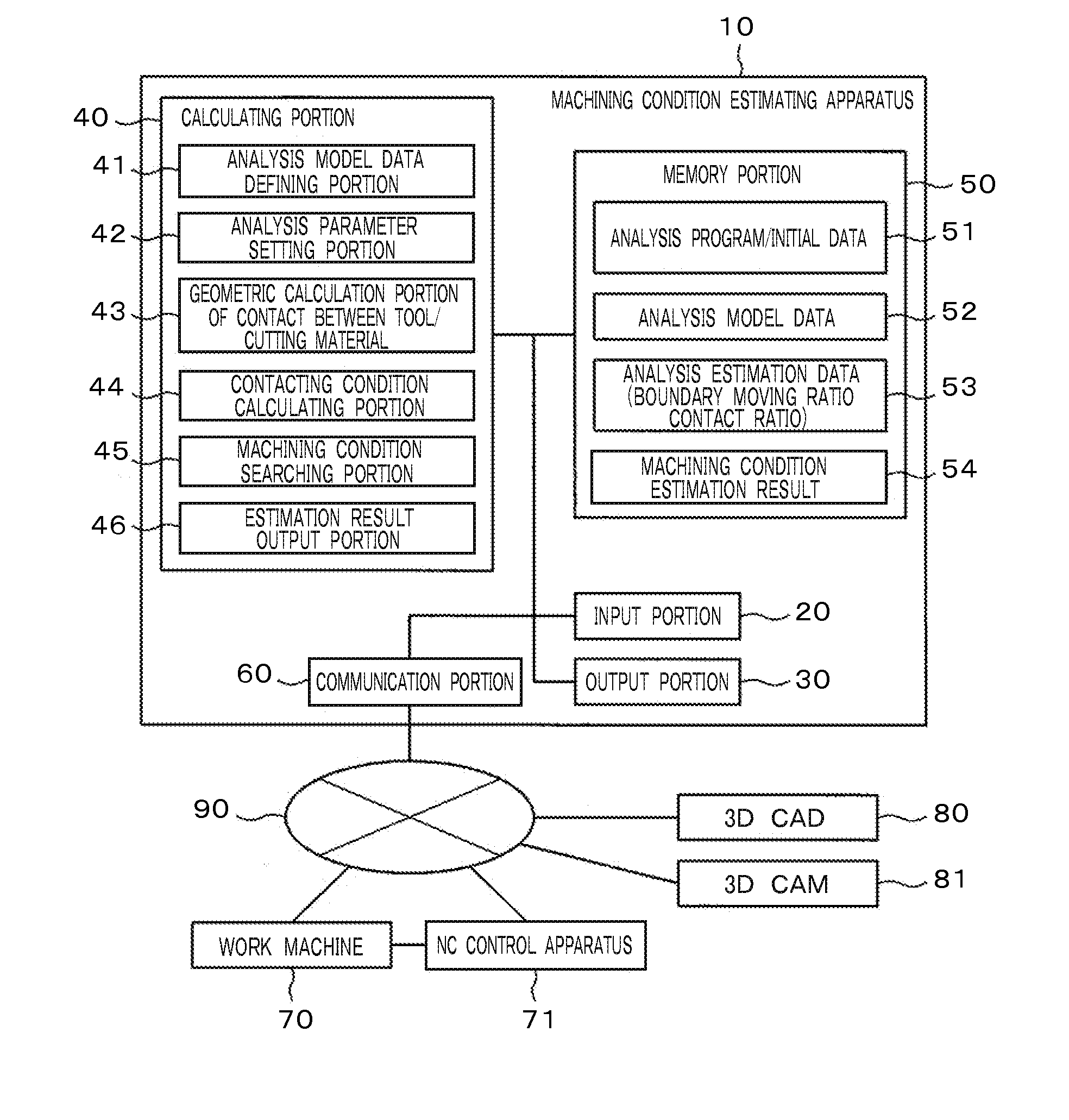
[0026]In the present embodiment, explanation will be given on a machining condition estimating apparatus 10 shown in FIG. 1, for estimating machining condition so as to extend a life-time of tools, with suppressing boundary wears of the tools applied in a work machine.

[0027]The machining condition estimating apparatus 10 comprises an input portion 20, an output portion 30, a calculating portion 40, a memory portion 50 and a communicating portion 60. The communicating portion 60 is connected with, for example, a work machine 70, a NC controlling apparatus 71, 3D CAD 80, 3D CAM 81, etc., via a network 90.

[0028]The calculating portion 40 comprises a tool to be attached on the work machine as a target of analysis, an analysis model data defining portion 41 for providing a user interface, for enabling a user to define model data of a material to be cut (hereinafter, “cutting material”) and an initial value / setup region for the machining condition, an analysis parameter setup portion 42 f...


PUM


Abstract

A machining condition estimating apparatus, for estimating a long life-time machining condition, by suppressing boundary wears, from among plural numbers of choices of machining conditions, without building up database, comprise: a means for defining an analysis model presenting shapes of a tool and a cutting material, to be a target of analysis, and various kinds of machining condition parameters relating to relative positions between the tool and the cutting material; a means for setting up an initial value for use of analysis and change volume of the machining condition parameter as analysis parameters; a means for conducting geometric calculation of contact length, over which the tool and the cutting material of the model contact with, for each analysis parameter; a means for producing a distribution waveform, plotting the contact length “Lci” for each position “γi” of a point on each blade edge calculated, on “γi”−“Lci” coordinates, thereby to calculate a ratio of movement length of a boundary portion with respect to the maximum contact length (boundary movement rate) and a ratio of width, over which a tool blade contacts with the cutting material (contact rate); a means for searching the analysis parameter, with which the boundary movement rate or the contact rate comes to maximum, respectively; and a means for outputting a long life-time machining condition selected from the analysis parameters searched.

Description

CLAIM OF PRIORITY[0001]The present application claims priority from Japanese Patent Application JP2013-006275 filed on Jan. 17, 2013, the content of which is hereby incorporated by reference into this application.BACKGROUND OF THE INVENTION[0002]1. Technical Field[0003]The present invention relates to a machining condition estimating apparatus for estimating a machining condition for suppressing wear of a tool in machining on a curved surface with applying a multi-axial work machine, and a machining condition estimating method for the same.[0004]2. Background Art[0005]A background technology of the present technical field is already known in Japanese Patent Laid-Open No. 2008-221454, for example. In this publication is described “to provide a method for estimating wear of a tool, so as to enable to estimate an amount of wear of the tool at high accuracy before machining, from a low-speed cutting region to a high-speed cutting region. Since the amount of wear of the tool is estimated...

Claims


Application Information

Patent Timeline
IPC IPC(8): G05B19/4065
CPCG05B19/4065G05B2219/49225
Inventor UTSUMI, KOJIFUJIHARA, SHIGEYOSHIKITAMURA, TADASHIINOUE, KENICHIKAYAMA, SHINJI
Owner HITACHI METALS LTD
Why Eureka
Try Eureka