
Electric machine tool and method for controlling the electric machine tool

a technology of electric machine tools and electric motors, which is applied in the direction of manufacturing tools, metal-working machine components, and portable power-driven tools, etc., can solve the problems of large accelerations of the rotational axis of the electric tool, unfavorable conditions, and large torque peaks that may occur under unfavorable conditions, so as to improve the operability of the machine tool

Active Publication Date: 2014-08-07
ROBERT BOSCH GMBH
View PDF6 Cites 35 Cited by
  • Summary
  • Abstract
  • Description
  • Claims
  • Application Information

AI Technical Summary

Benefits of technology

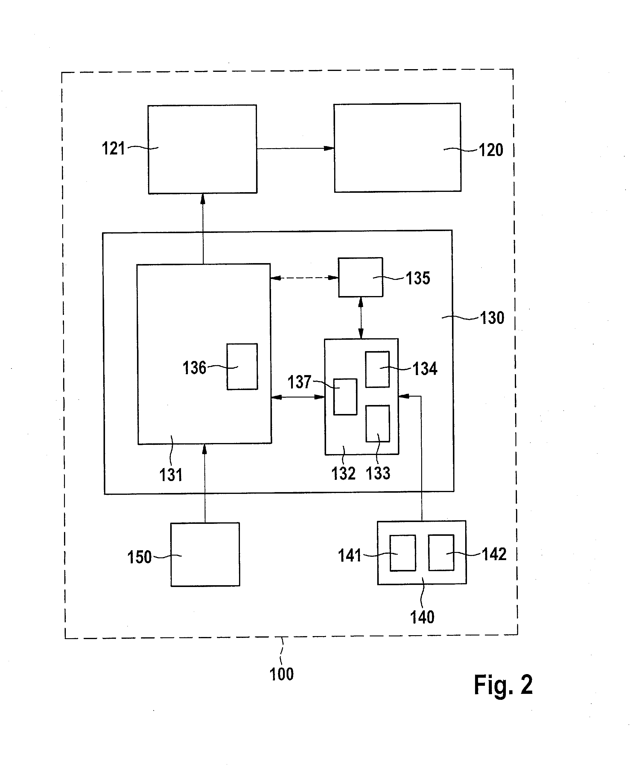
This patent is about improving the operation of an electric machine tool by detecting parameters and evaluating the tool's operating state in various modes. A protective function is activated when a critical operating situation is detected. The method includes detecting the mode of operation and adapting the evaluation method accordingly to reliably recognize critical situations. Different evaluation methods and devices are associated with each operating mode for better recognition and detection of critical situations. The use of multiple evaluation devices also allows for a faster response by the control device. Overall, this improves user safety and simplifies the operation of the machine tool.

Problems solved by technology

In particular, very high torque peaks may occur under unfavorable conditions.
In particular for high-power machine tools, these torque peaks may represent hazardous working situations for the user.
However, even for less high-power machine tools which are operated at a very high rotational speed, very large accelerations which last for several milliseconds may occur about the rotational axis of the electric tool due to the high level of rotational energy that is present in the system when the insertion tool suddenly becomes jammed.
On the other hand, in certain cases it is not possible to recognize, or correctly recognize, occurring kickback events based on the predefined evaluation criteria.

Method used


Image

  • Electric machine tool and method for controlling the electric machine tool
  • Electric machine tool and method for controlling the electric machine tool
  • Electric machine tool and method for controlling the electric machine tool

Examples


Embodiment Construction

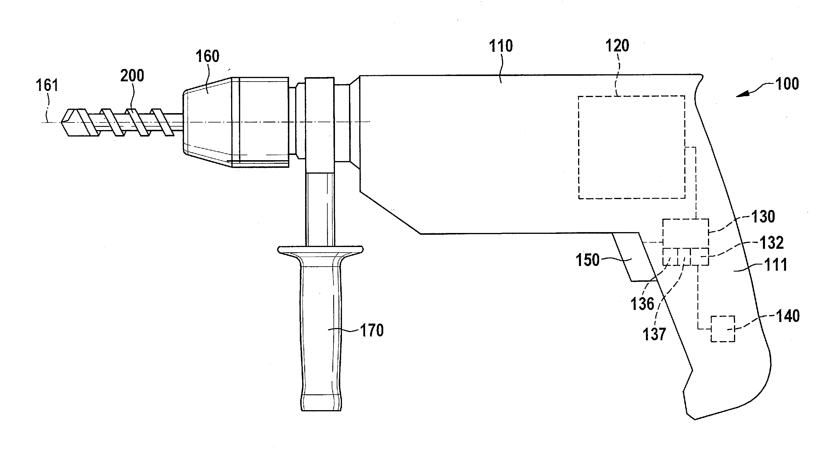
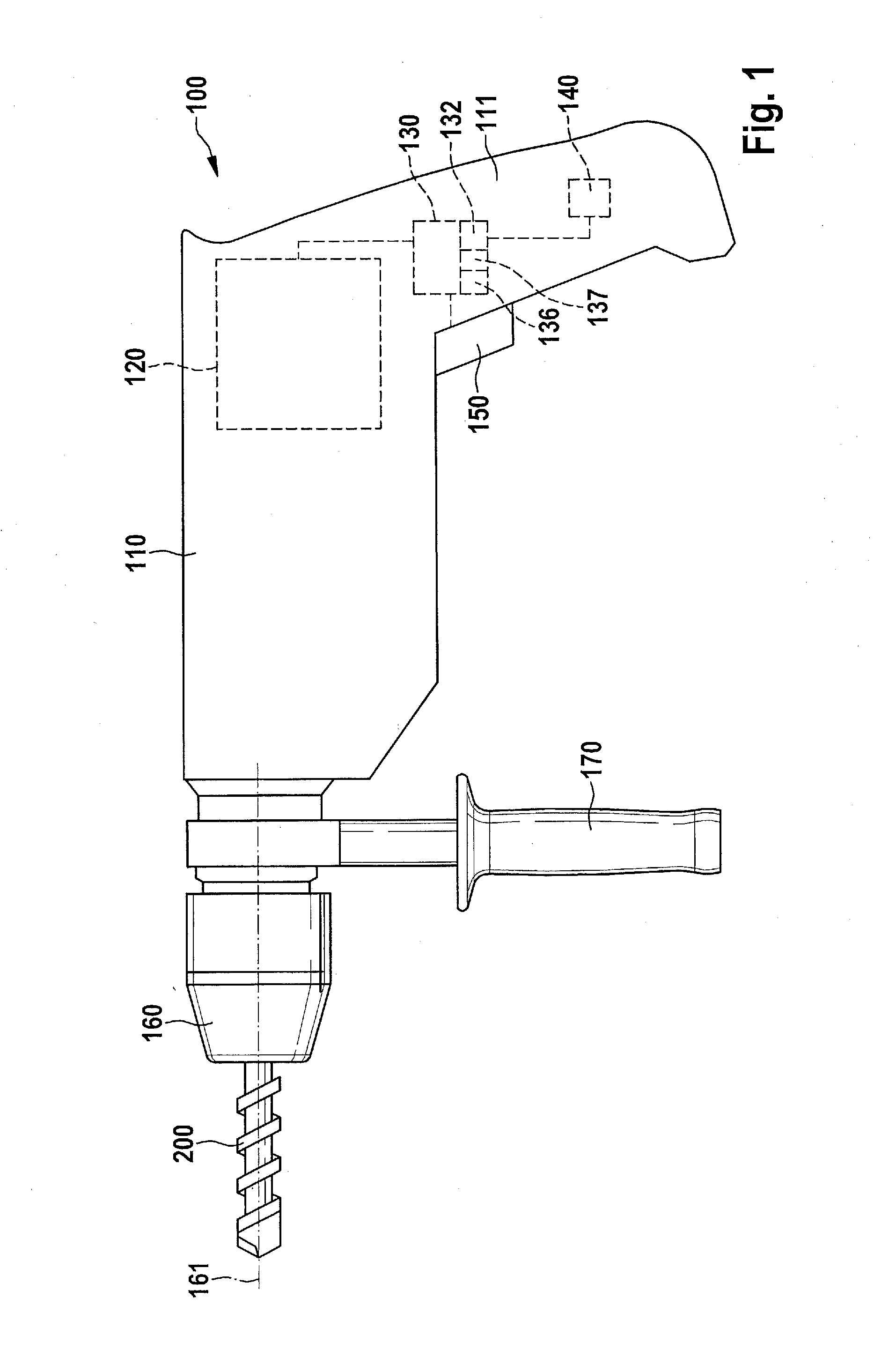
[0022]Electric machine tools having exchangeable insertion tools, for example drills, hammer drills, cordless screwdrivers, cordless drills, or similar devices equipped with appropriate insertion tools, are typically equipped with a high-power electric motor for driving the insertion tool. FIG. 1 shows an example of a machine tool 100 designed as a drill, having an insertion tool 200 which is designed as a drill bit and which is fastened in a drill chuck 160 of drill 100. Drill 100 has a typical housing 110 with a housing section which forms a handle 111. Electric motor 120 accommodated in the middle part of device housing 110 drives insertion tool 200 clamped in drill chuck 160, in a rotating manner about a predefined rotational axis 161, typically via a conversion gear (not illustrated here). For controlling the operation of electric motor 120, drill 100 has a control device 130 and at least one control element 150, which in FIG. 1 is designed as a main switch as an example only, ...


PUM


Abstract

In a method for controlling an electric machine tool having an electric motor for driving a rotating insertion tool, the electric machine tool is operated in one of multiple operating modes, and at least one parameter of the machine tool is detected. The instantaneous operating state of the electric machine tool is ascertained and evaluated based on the detected parameter. A protective function is activated when the presence of a critical operating situation is recognized during the evaluation of the instantaneous operating state. The instantaneous operating mode of the electric machine tool is detected, and the evaluation of the instantaneous operating state is adapted in each case to the instantaneous operating mode.

Description

BACKGROUND OF THE INVENTION[0001]1. Field of the Invention[0002]The present invention relates to an electric machine tool having an electric motor for driving a rotating insertion tool, and to a method for controlling the electric machine tool.[0003]2. Description of the Related Art[0004]Electric machine tools such as drills or hammer drills are equipped with exchangeable insertion tools which are typically driven in a rotating manner by an electric motor of the machine tool. During operation of such a hand tool, the torque which occurs at the machine due to the rotation of the insertion tool is compensated for by a countertorque to be applied by the user. Depending on the operating situation, the torque load on the user may vary greatly. In particular, very high torque peaks may occur under unfavorable conditions. This is the case, for example, for a so-called kickback event in which the insertion tool becomes jammed in the workpiece. In particular for high-power machine tools, the...

Claims


Application Information

Patent Timeline
Patent Type & Authority Applications(United States)
IPC IPC(8): B25F5/00B23Q11/00
CPCB23Q11/0092B25F5/00B23Q11/0085
Inventor STEURER, CHRISTOPH
Owner ROBERT BOSCH GMBH
Learn More