
Heated and cooled chair apparatus

a chair and apparatus technology, applied in the field of chairs, can solve the problems of reducing the heat transfer efficiency of the body affecting the efficiency of heat transfer to or from the chair, so as to improve the efficiency of the chair heating system, reduce radiant heat loss, and improve the heating and cooling effect of the sea

Active Publication Date: 2014-08-07
RGT UNIV OF CALIFORNIA
View PDF15 Cites 45 Cited by
  • Summary
  • Abstract
  • Description
  • Claims
  • Application Information

AI Technical Summary

Benefits of technology

The patent is about a chair with a special covering that allows moisture to evaporate from the person's body. This covering can be made from a lightweight material that controls how quickly the sweat is removed. The chair also has a cooling system that can be adapted to different chairs and furniture designs. This invention is cost-effective and can help to make chairs more comfortable for people.

Problems solved by technology

However, the rate and efficiency of heat transfers to or from a body and a chair can be negatively influenced by a number of factors.
Second, the evaporation rate of body perspiration may be reduced by vapor resistance imparted by the surface, padding, and structure of the chair, resulting in diminished heat transfer from the body.
Third, the chair may block the radiant emissions from the surrounding room surfaces.
Fourth, the chair's conductive properties and thermal capacitance affect the rate of heat transfer out of the seated person when the chair is colder than the clothing temperature, or into the person when the chair is hotter than the clothing temperature.
Consequently, the thermal requirements of some occupants may not be satisfied simply by ambient air temperature control.
While the environment may be comfortable to some people, the temperature of the conditioned air or of the environment may be too cold or too hot for other people.
For example, the temperature of a seat in a vehicle or in an enclosed room that has been exposed to the sun for a prolonged period of time can become very hot and may remain hot for a period of time even with exposure to air-conditioned air.
Likewise, a vehicle seat that has been exposed to winter weather may be very cold and uncomfortable for the occupant requiring the introduction of hot air that greatly exceeds the comfort level of the occupant in order for the rate of temperature change in the seat and interior to be accelerated.
Even with the introduction of extremely conditioned air, the seat temperatures and the perceived interior temperatures may be slow to change because large portions of the body of the occupant of the seat isolate the seat and the body from the heat transfer effects of the conditioned air.
Accordingly, the thermal comfort of stationary, seated occupants may not be provided comfortably or efficiently with the introduction of temperature controlled air into the environment.
One problem experienced by ventilated seat systems is that prolonged exposure to the forced cooled supply air on the body can overcool back muscles and cause back spasms.
The contact area of the occupant can also decrease the total flow of air through the seat perforations and diminish the effectiveness of the convection mechanism for heating or cooling the occupant.
Another problem with systems that force air through perforations in the seat surfaces is the need for a relatively high pressure source of temperature modified air, through fans and distribution system that can accommodate the pressure drop across the perforated surface and provide a sufficient air flow.
A further problem with the conventional ventilated seats is the noise that is created by the fans that are part of a pressurized air distribution system that is audible through the surface of the seat.
The noise created by the fans, air ducts and air conditioning devices increases with the desired airflow and size of the system to overcome the big pressure drop through the perforated seat surface.

Method used


Image

  • Heated and cooled chair apparatus
  • Heated and cooled chair apparatus
  • Heated and cooled chair apparatus

Examples


Embodiment Construction

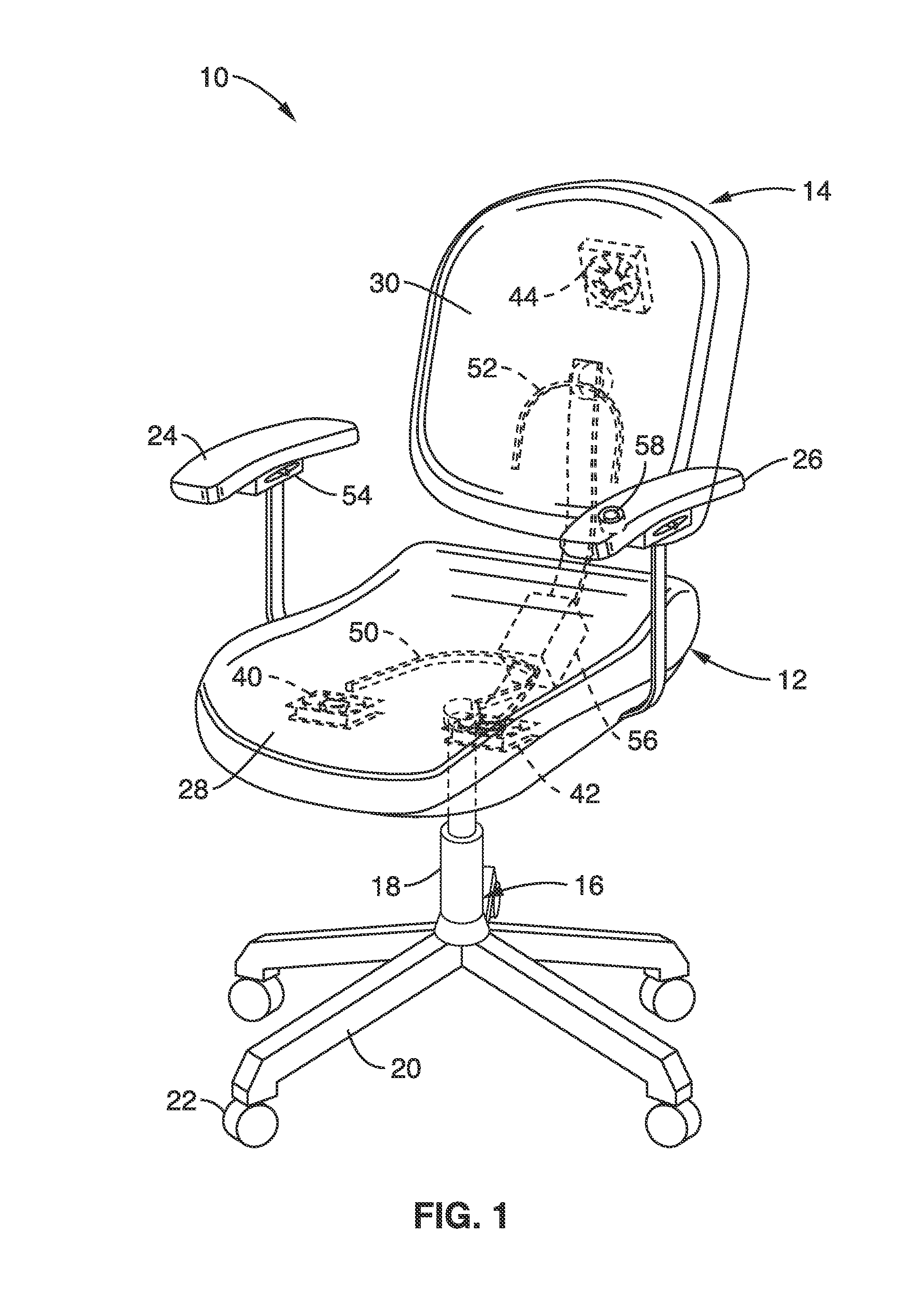
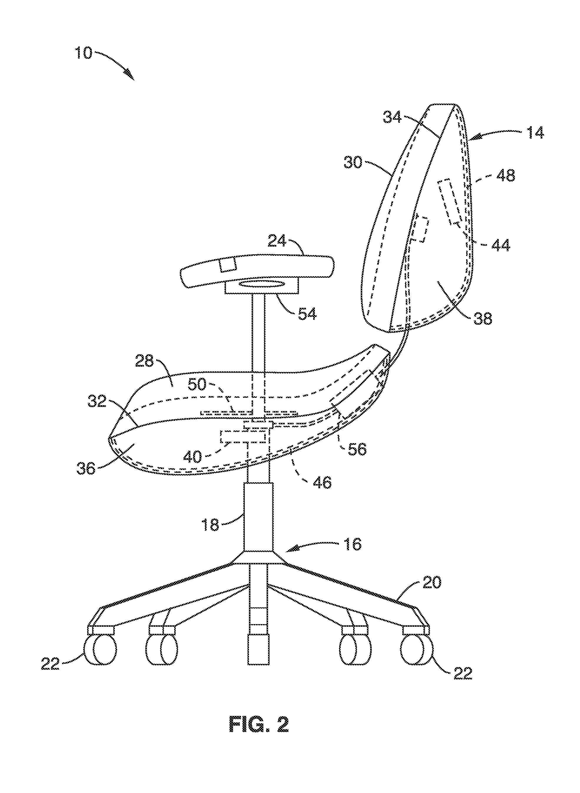
[0047]Referring more specifically to the drawings, for illustrative purposes an embodiment of a heated and cooled chair for energy efficient personal comfort of the present invention is depicted generally in FIG. 1 through FIG. 4. It will be appreciated that the system may vary as to the elements, specific steps and sequence and the apparatus structure may vary as to structural details, without departing from the basic concepts as disclosed herein.

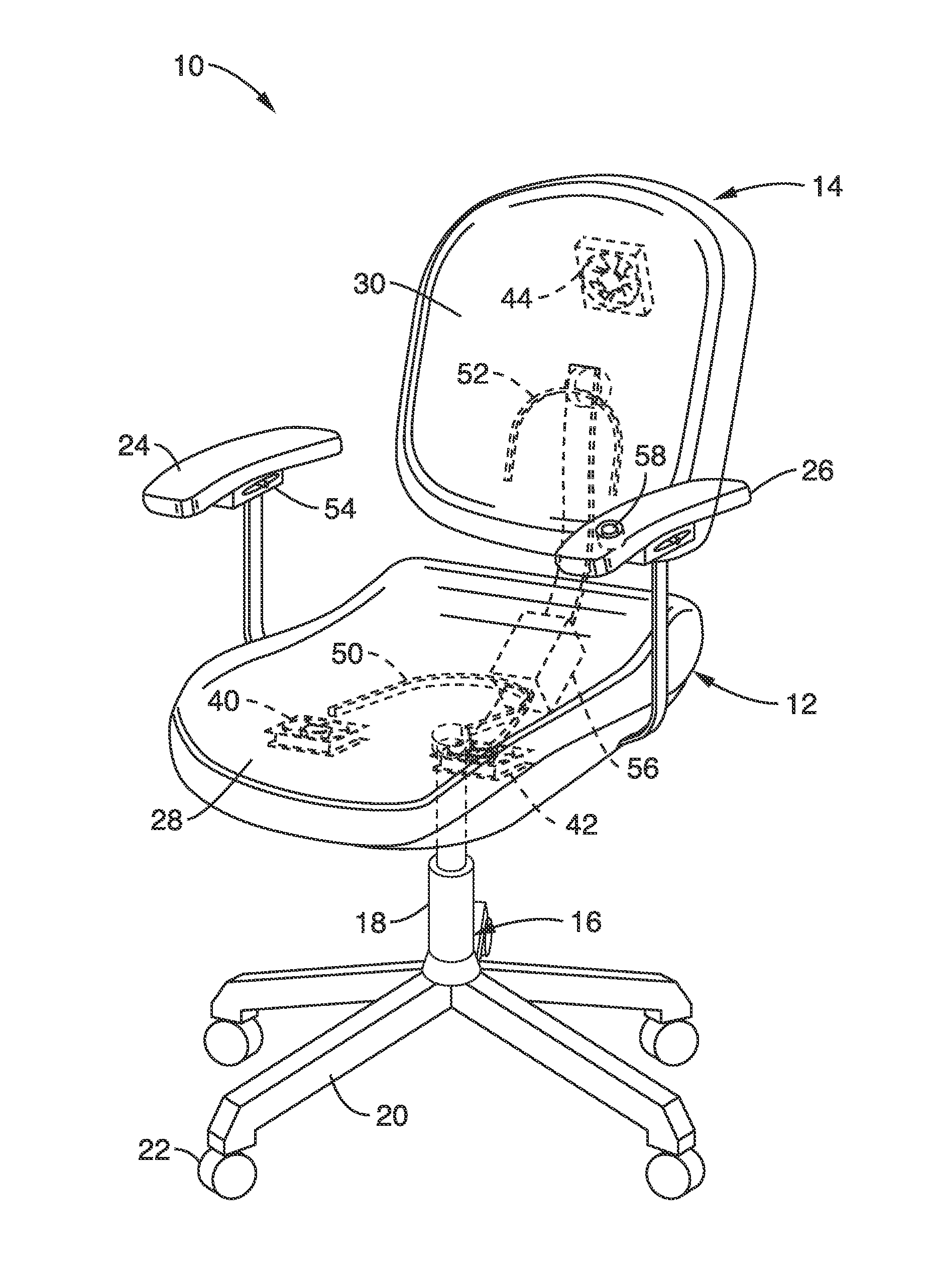
[0048]Turning now to FIG. 1 through FIG. 3, an embodiment of a chair 10 with an occupant heating and cooling system is schematically shown. The chair 10 used to illustrate the invention is a typical office desk chair with a generally horizontal seat 12 and a generally vertical back rest 14 that are mounted to a base 16. The seat 12 and the back rest 14 can be separate features as shown in FIG. 1 through FIG. 3 or the seat and the back rest can be joined together on one edge. Although a desk chair design is used to illustrate the invention,...


PUM


Abstract

Articles of furniture with a system of heating and cooling that can be integrated into a building environmental control network are provided. The heating / cooling system of the article has surfaces of a porous or non-porous, moisture-permeable material allowing convective and evaporative heat exchange from the body surface to the environment. The material covers a plenum that has reflective surfaces to reduce radiant losses and low-wattage fans to circulate air that convectively cools the occupant. Resistance heating may be incorporated at key occupant contact areas in the seat and backrest. Temperature, occupancy and other sensors can be incorporated. A control interface controls the actions of the heating / cooling system of the article and can interact with a network server to transmit measurements of environmental temperatures and occupant selection of control settings that are useful for control of the building's indoor environment.

Description

CROSS-REFERENCE TO RELATED APPLICATIONS[0001]This application claims the benefit of U.S. provisional patent application Ser. No. 61 / 760,545 filed on Feb. 4, 2013, incorporated herein by reference in its entirety.STATEMENT REGARDING FEDERALLY SPONSORED[0002]RESEARCH OR DEVELOPMENT[0003]Not ApplicableINCORPORATION-BY-REFERENCE OF MATERIAL SUBMITTED IN A COMPUTER PROGRAM APPENDIX[0004]Not ApplicableBACKGROUND OF THE INVENTION[0005]1. Field of the Invention[0006]This invention pertains generally to seating assemblies and more particularly to chairs with devices for occupant temperature control and thermal comfort.[0007]2. Description of Related Art[0008]Thermal comfort of individuals in living or working spaces is typically provided by modifying the temperature of the ambient air and the temperature of the surrounding surfaces in the indoor environment. Heating and cooling systems in a building produce temperature and humidity modified air that is normally distributed to the interior en...

Claims


Application Information

Patent Timeline
Patent Type & Authority Applications(United States)
IPC IPC(8): A47C7/74
CPCA47C7/748A47C7/744
Inventor ARENS, EDWARD A.ZHANG, HUIPASUT, WILMER
Owner RGT UNIV OF CALIFORNIA
Learn More