
Motor Control Device

a control device and motor technology, applied in the direction of capacitor control, dynamo-electric converter control, instruments, etc., can solve the problems of difficult detection of ccvs of all secondary battery cells, gradual accumulation of errors, etc., to reduce battery cost, simplify structure and control of battery cells, and calculate soc further accurately

Active Publication Date: 2014-08-07
HITACHI ASTEMO LTD
View PDF9 Cites 22 Cited by
  • Summary
  • Abstract
  • Description
  • Claims
  • Application Information

AI Technical Summary

Benefits of technology

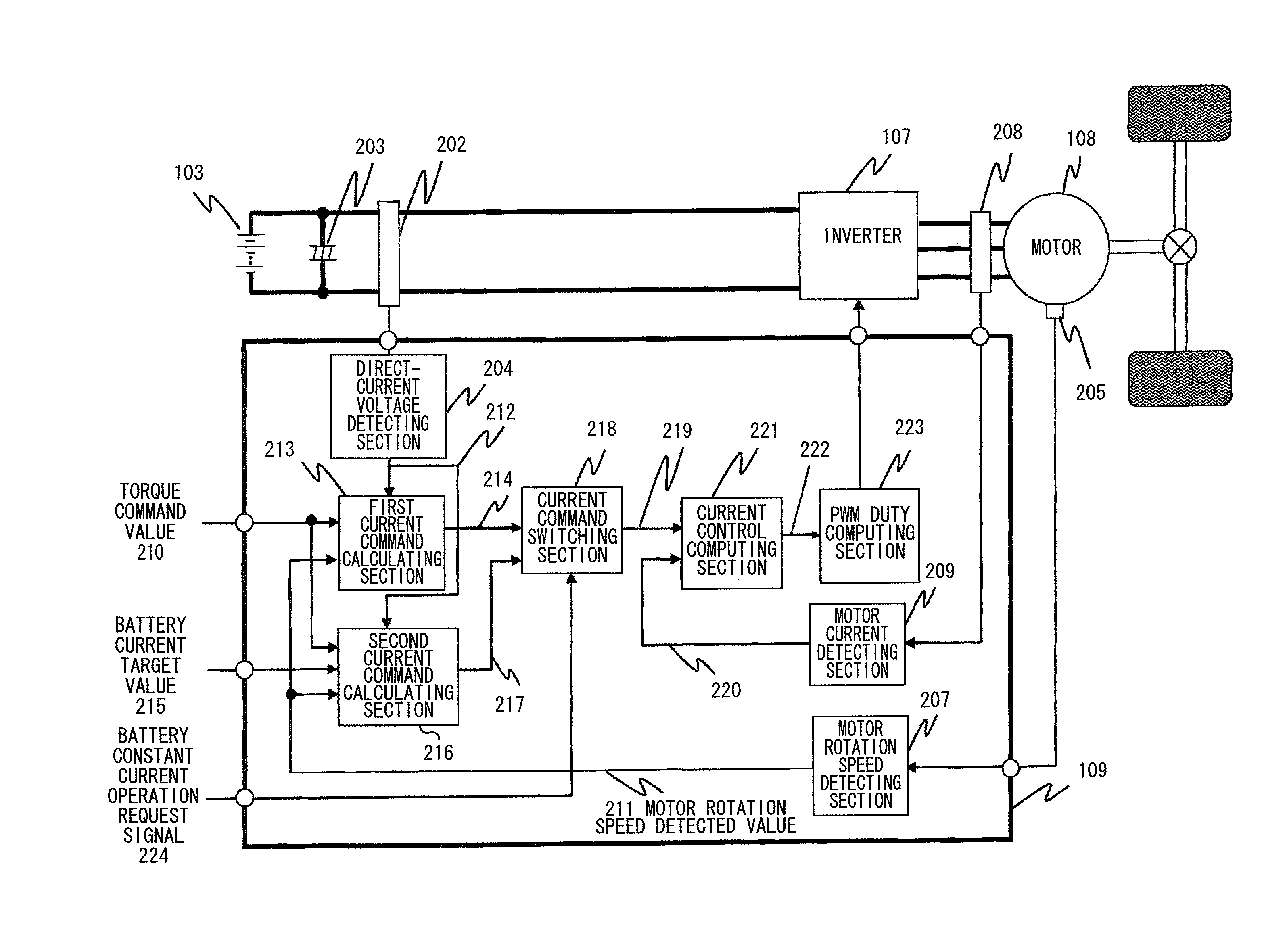
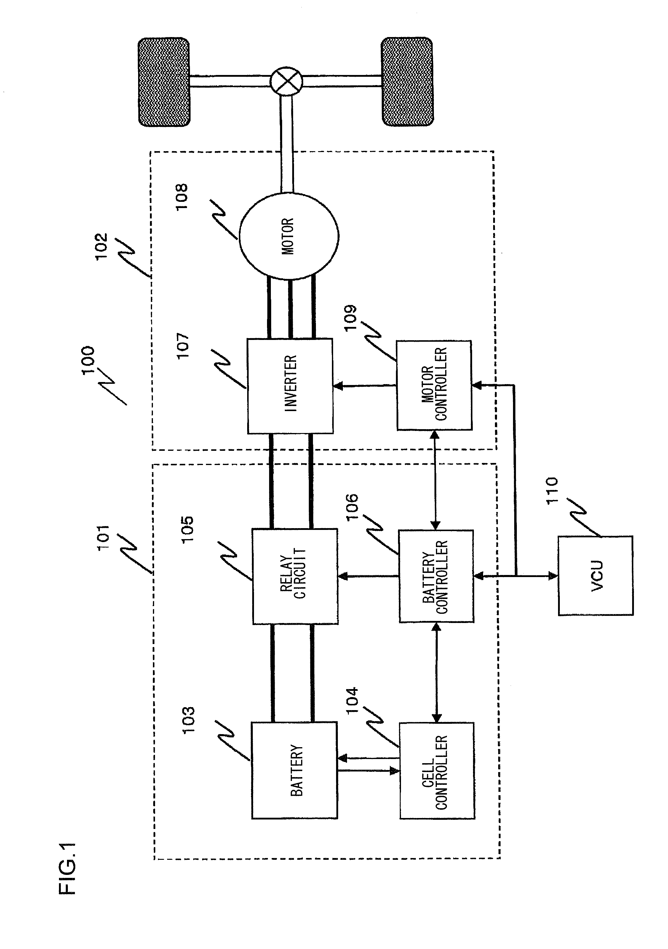
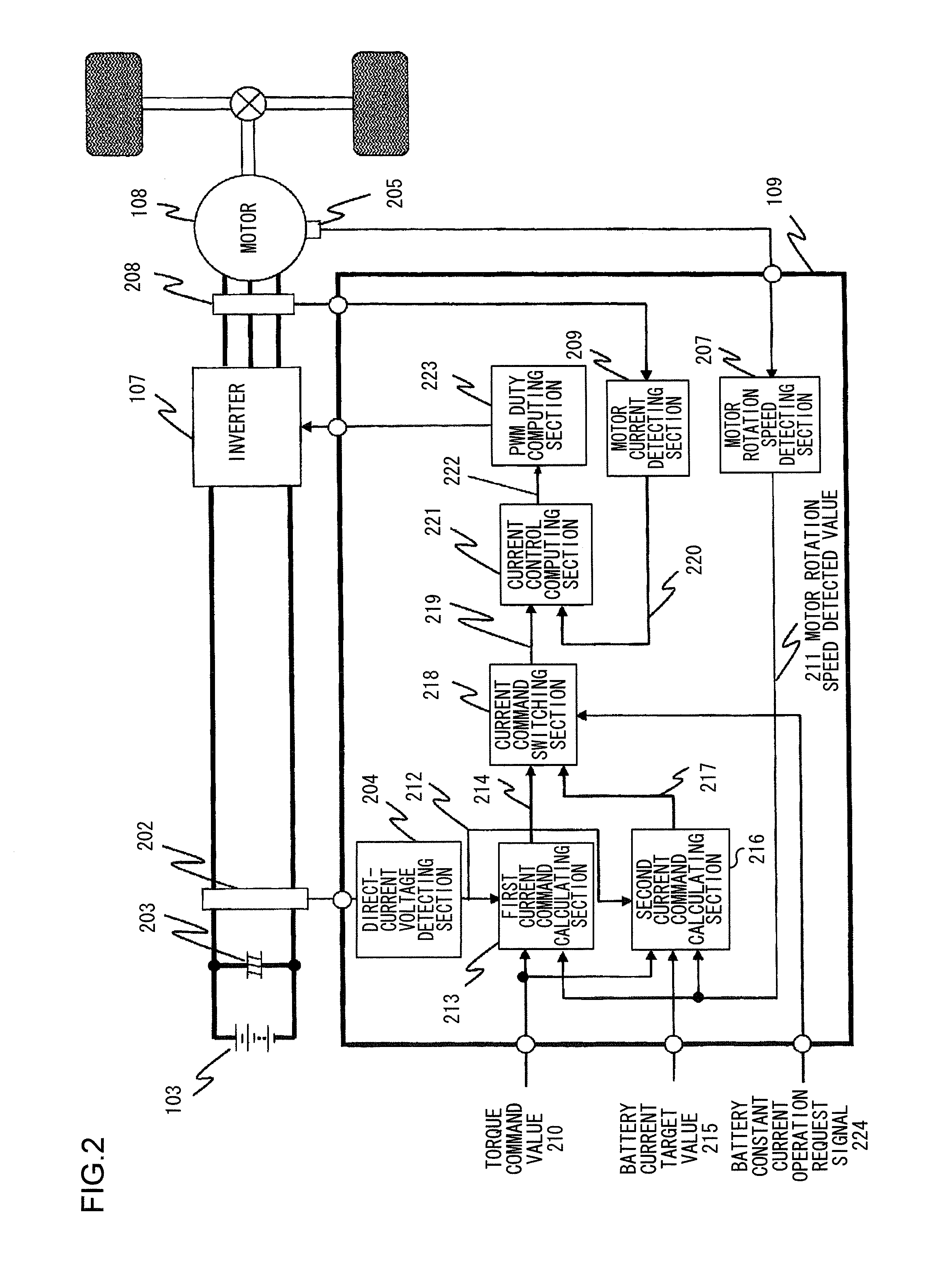
The invention is a motor control device that allows for accurate measurement of the battery's capacity and state of health (SOH) using a single battery. This simplifies the device's structure and reduces costs.

Problems solved by technology

However, because charging and discharging are frequently repeated during traveling of the vehicle, it is difficult to detect the CCVs of all the secondary battery cells in an identical condition, and an error occurs to a certain extent in detection of the CCV of the each secondary battery cell.
The error in the detection of battery voltage values of these secondary battery cells is accumulated, an error is also produced in the calculated SOC of the battery with respect to the actual SOC, and this error is gradually accumulated.

Method used


Image

  • Motor Control Device
  • Motor Control Device
  • Motor Control Device

Examples


first example

[0086]FIG. 7 is a flowchart for explaining the constant current operation permission in the motor control device when a vehicle is in a hill-hold travel.

[0087]The external controller 110 determines whether or not the vehicle is currently in the hill-hold travel (a step S701). If it is determined that the vehicle is in the bill-hold travel (YES in the step S701), a battery constant current operation permission status is set to “PERMITTED” (a step S703).

[0088]On the other hand, if the vehicle is not in the hill-hold travel (NO in the step S701), the battery constant current operation permission status is set to “PROHIBITED” (a step S702). The external controller 110 transmits the battery constant current operation status to the motor controller 109 and the battery controller 106 (a step S704).

second example

[0089]FIG. 8 is a flowchart for explaining the constant current operation permission in the motor control device when the vehicle is in a hill-climb travel.

[0090]The external controller 110 determines whether or not the vehicle is currently in the hill-climb travel (a step S801). If it is determined that the vehicle is in the hill-climb travel (YES in the step S801), the battery constant current operation permission status is set to “PERMITTED” (a step S803).

[0091]On the other hand, when the vehicle is not in the hill-climb travel (NO in the step S801), the battery constant current operation permission status is set to “PROHIBITED” (a step S802). The external controller 110 transmits the battery constant current operation status to the motor controller 109 and the battery controller 106 (a step S804).

third example

[0092]FIG. 9 is a flowchart for explaining the constant current operation permission in the motor control device when the vehicle is in a downhill travel. When the vehicle is in the downhill travel at the constant speed, the motor 108 does not operate by receiving the AC current from the inverter 107 but performs the regenerative operation. However, due to the constant speed, a power generation amount of the motor 108 is constant, and the DC current flowing through the battery 103 is stabilized as in the constant current operation of the motor 108; therefore, the CCV of the secondary battery cell that forms the battery 103 can be measured accurately.

[0093]The external controller 110 determines whether or not the vehicle is currently in a downhill travel (a step S901). If it is determined that the vehicle is in the downhill travel (YES in the step S901), the battery constant current operation permission status is set to “PERMITTED” (a step S903).

[0094]If the vehicle is not in the dow...


PUM


Abstract

A motor control device according to the invention includes: a mode setting section that sets one of a first mode in which a charge / discharge current of a secondary battery varies according to load fluctuation of a motor and a second mode in which the charge / discharge current of the secondary battery becomes constant for a predetermined time regardless of the load fluctuation of the motor; and a drive signal generating section that generates a drive signal for driving the motor on the basis of the mode that is set by the mode setting section, a torque command value, and a motor rotation speed.

Description

TECHNICAL FIELD[0001]The present invention relates to a motor control device.BACKGROUND ART[0002]In general, multiple electric motors are mounted in an electric drive vehicle such as a hybrid electric vehicle (HEV) and an electric vehicle (EV), and particularly, a high-power electric motor is used as a driving force. As a power source that supplies power to the electric motor used as the driving force, a battery that is formed of a battery pack including plural secondary battery cells such as nickel hydrate battery cells or lithium battery cells is used. A State of Charge (SOC) is used as a parameter that indicates a charging state of the battery. For estimating the SOC during traveling of a vehicle, in general, a method is widely used in which open circuit voltage OCV is calculated from closed circuit voltage CCV during traveling of the vehicle, polarization voltage, internal resistance, and a battery current integrated value and in which the SOC is estimated from the thus-calculat...

Claims


Application Information

Patent Timeline
Patent Type & Authority Applications(United States)
IPC IPC(8): H02P27/06
CPCH02P27/06B60L15/20B60L2240/421B60L2240/423B60L2240/425B60L2240/547B60L2240/549H01M10/441H01M10/482G01R31/007B60L3/12B60L7/14B60L15/2045B60L2240/12B60L2240/14B60L2240/427B60L2240/429B60L2240/545B60L2240/642B60L2250/26B60L2260/26Y02T90/16B60L50/40B60L50/51B60L58/10B60L58/12G01R31/3835B60L58/18Y02T10/64Y02T10/70Y02T10/72Y02E60/10B60L3/0046
Inventor MATSUI, HIROKAZUYAMADA, HIROYUKI
Owner HITACHI ASTEMO LTD
Learn More