Systems and methods for battery life maximization under fixed-route applications

a technology of fixed route and battery life, applied in the direction of battery/fuel cell control arrangement, charging station, transportation and packaging, etc., can solve the problems of affecting the life of batteries, affecting the safety of electric vehicles, and unable to enable electrical vehicles to run independently of railings or overhead lines. , to achieve the effect of maximizing soc cycling, maximizing battery life of electric vehicles, and less damag

Active Publication Date: 2014-08-07
PROTERRA OPERATING CO INC
View PDF4 Cites 68 Cited by
  • Summary
  • Abstract
  • Description
  • Claims
  • Application Information

AI Technical Summary

Benefits of technology

[0005]Embodiments of the invention provides systems and methods for maximizing the battery life of electric vehicles by maximizing SOC cycling in less damaging areas of the SOC range. Various aspects of embodiments of the invention described herein may be applied to any of the particular applications set forth below or for any other types of vehicles or power sources or for any application requiring rapid charging of an energy storage system. Embodiments of the invention may be applied as a standalone system or method, or as part of an integrated transportation system, such as a bus system or other public transportation system. It shall be understood that different aspects of the invention can be appreciated individually, collectively, or in combination with each other.

Problems solved by technology

Recent trends in integrated transportation systems for electric vehicles, such as bus systems or other public transportation systems, have moved away from the use of permanent electrical connections to electric vehicles, as these systems are an eyesore, are unpopular, are costly to install and maintain, and can be unsafe.
Some of these systems do not enable an electrical vehicle to run independent of a railing or overhead line.
However, such a charging strategy may result in cycling of the batteries within a state of charge (SOC) range that may be damaging or detrimental for the life of the batteries.

Method used


Image

  • Systems and methods for battery life maximization under fixed-route applications
  • Systems and methods for battery life maximization under fixed-route applications
  • Systems and methods for battery life maximization under fixed-route applications

Examples


Embodiment Construction

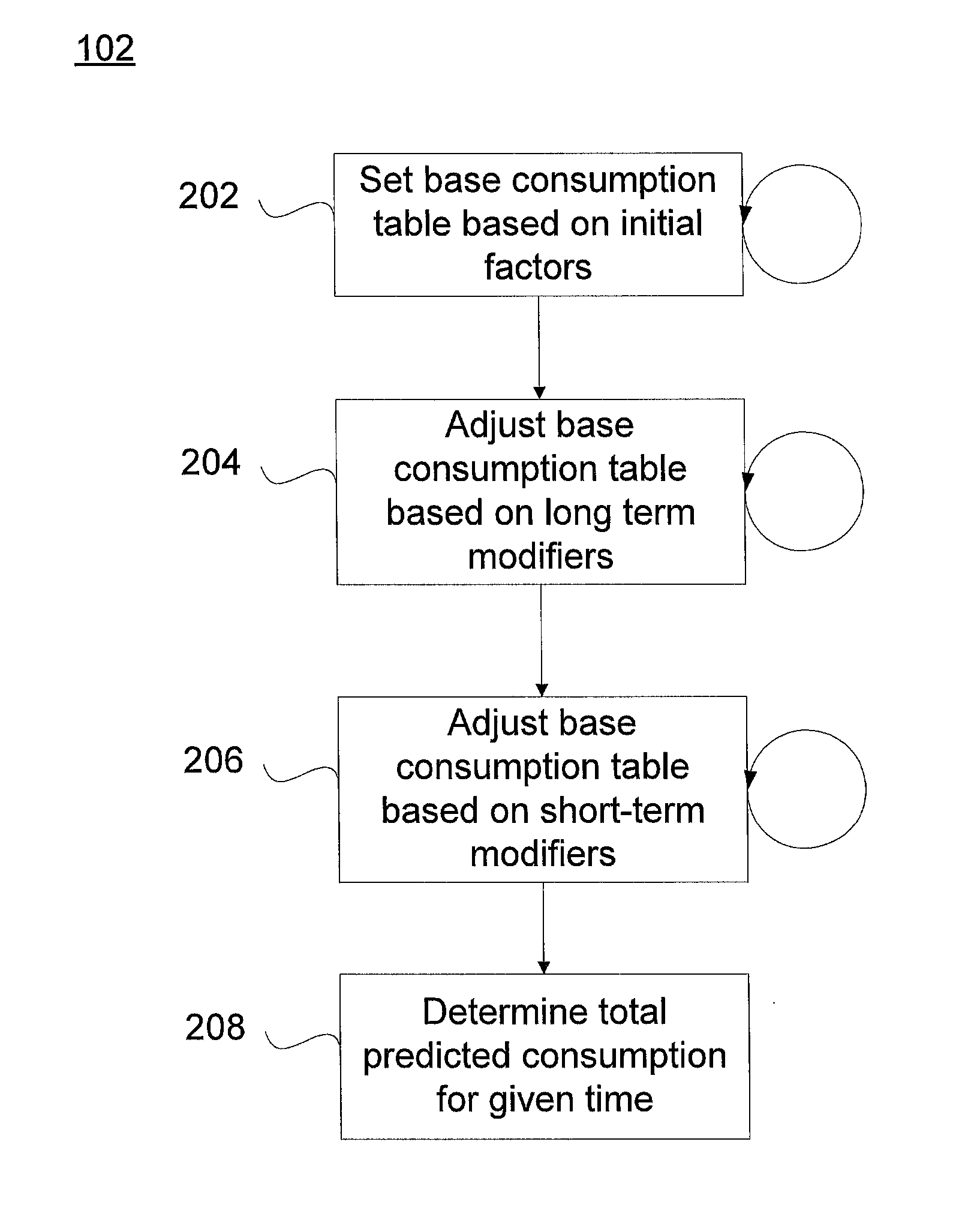
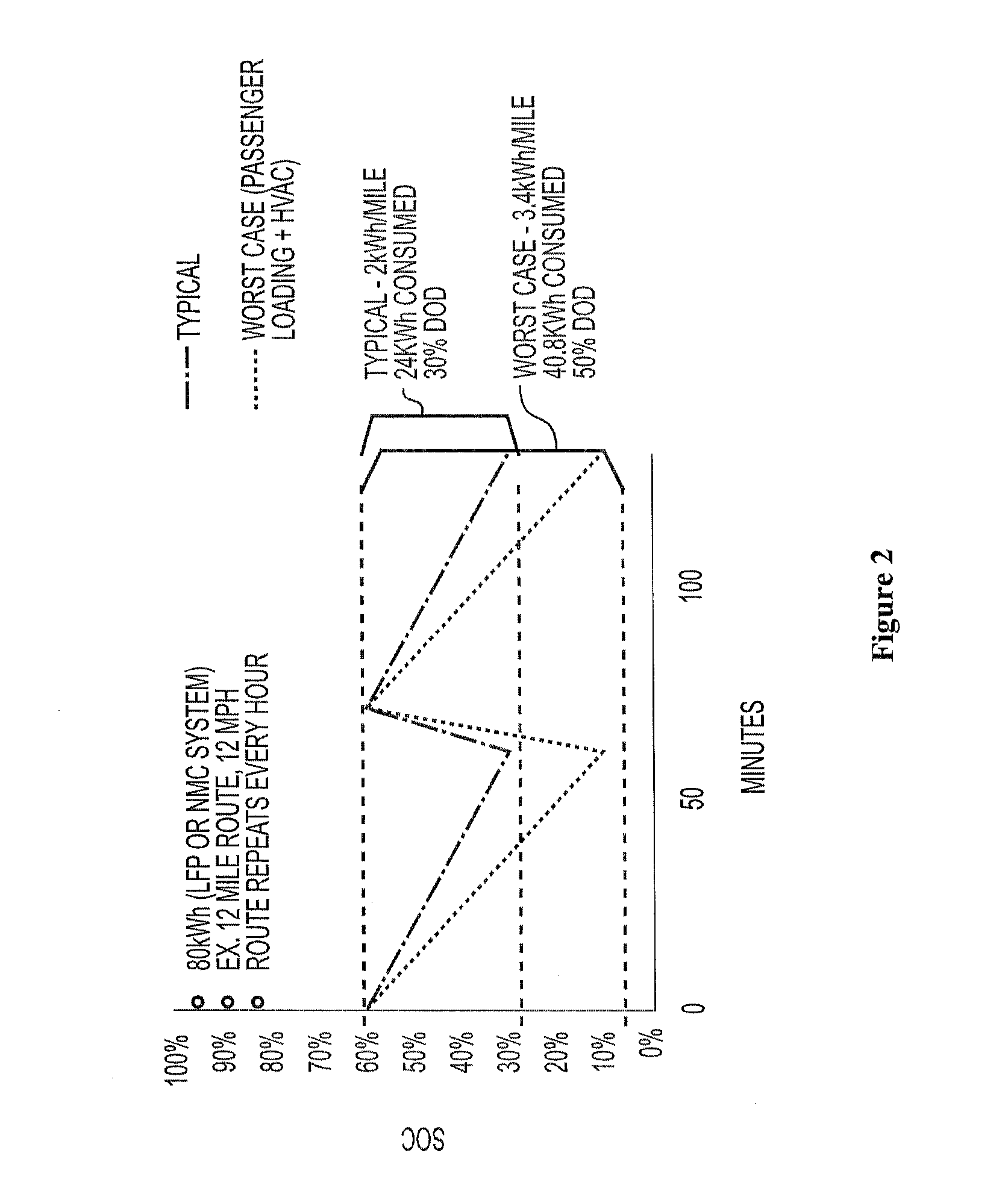
[0034]The invention provides systems and methods for maximizing the battery life of electric vehicles by maximizing SOC cycling in less damaging areas of the SOC range. Various aspects of the invention described herein may be applied to any of the particular applications set forth below, for electric or hybrid vehicles, or for any other types of vehicles. Various aspects of the invention described herein may be applied to any of the particular applications set forth below or for any other types of vehicles or power sources or for any application requiring rapid charging of an energy storage system. The invention may be applied as a standalone system or method, or as part of an integrated vehicle system. It shall be understood that different aspects of the invention can be appreciated individually, collectively, or in combination with each other.

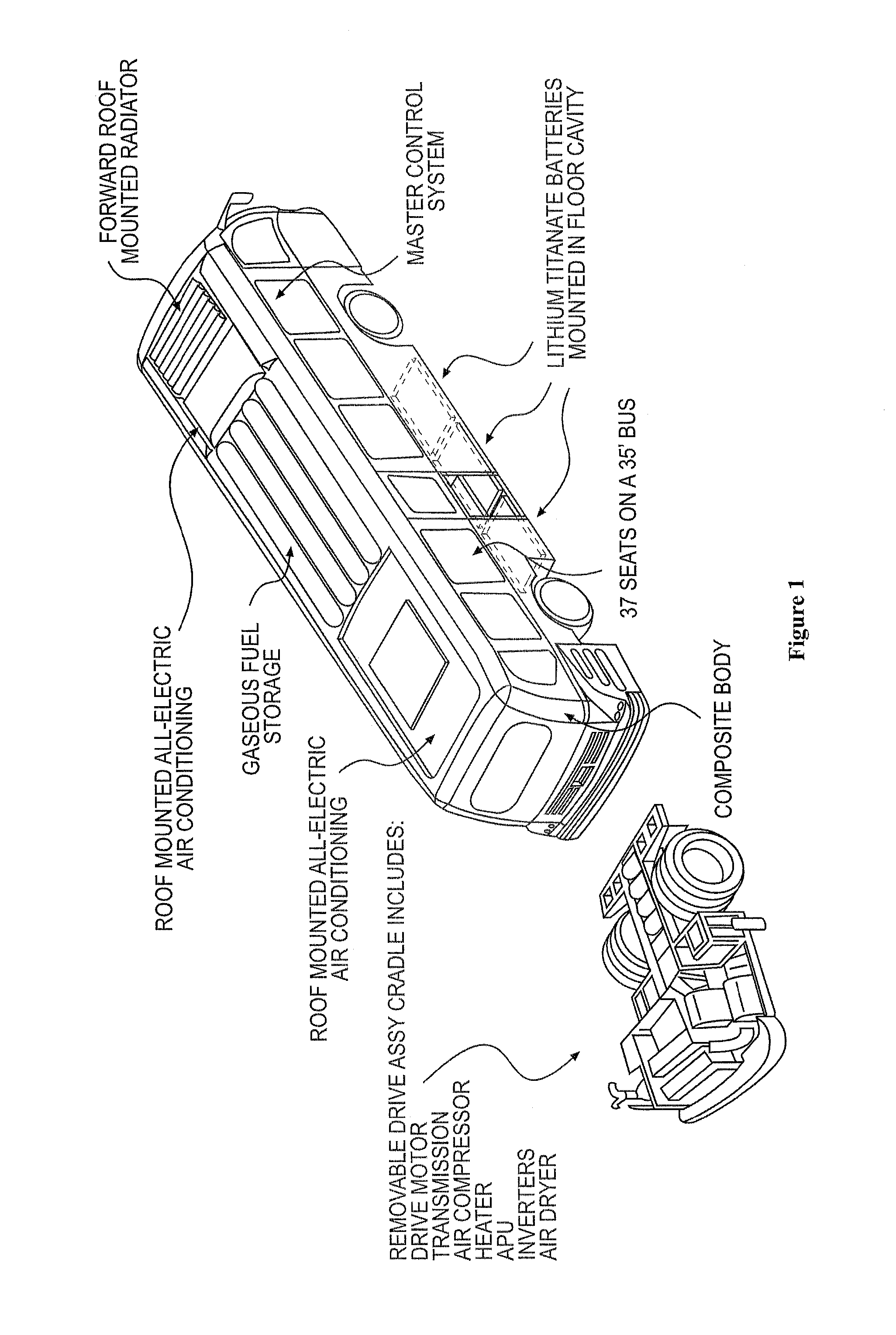
[0035]For example, electric vehicles powered by the system may include a transit bus with various features as shown in the schematic in FIG....


PUM


Abstract

An embodiment of the invention provides a method of charging an energy storage system for an electric vehicle. The method includes determining the estimated consumption for a specific route of the electric vehicle at different times and setting a target end point for the energy storage system based upon a minimum state of charge level for the energy storage system. The method further includes determining charge set points for the energy storage system based upon the target end point and the determined estimated consumption and determining the actual end point of the energy storage system after operation of the electric vehicle on the given route. The method also includes comparing the actual end point to the target end point and determining the difference in state of charge for the energy storage system between the actual end point and the target end point. In addition, the method includes using the difference between the actual end point and the target end point to adjust the charge set points for the energy storage system.

Description

BACKGROUND[0001]In recent years, hybrid and electric vehicles, which are provided with a battery, have been proposed, and some of them have been put into practice, to effectively use energy, in particular, regenerative energy as environmental measures. Typically, secondary batteries, which have been put to into practice and installed in vehicles so far, include, for example, lead storage batteries, nickel metal hydride batteries, or high powered lithium ion batteries. Some electric vehicles, such as electric cars, charge their batteries by plugging in the electric vehicle at a charging station. Other electric vehicles such as electric trains and light rail cars, are permanently connected to a power source through hardware in the railing or through overhead lines.[0002]Recent trends in integrated transportation systems for electric vehicles, such as bus systems or other public transportation systems, have moved away from the use of permanent electrical connections to electric vehicle...

Claims


Application Information

Patent Timeline
Patent Type & Authority Applications(United States)
IPC IPC(8): B60L11/18
CPCB60L11/1809B60L15/2045B60L2200/18B60L2200/26B60L53/00B60L53/32B60L58/13B60L53/54H02J2310/48Y02T10/64Y02T10/70Y02T10/7072Y02T90/14Y02T10/72Y02T90/12
Inventor MCGRATH, SEAMUSSARKAR, REUBENFINNERN, MICHAEL
Owner PROTERRA OPERATING CO INC
Why Eureka
Try Eureka