Converter circuit and method for transferring electrical energy

a technology of electrical energy and converter circuit, applied in the direction of electric devices, battery/fuel cell control arrangement, transportation and packaging, etc., can solve the problems of increasing the amount of technical complexity, and achieve the effect of reducing the reactive power removed from the ac voltage source and/or the sink

Inactive Publication Date: 2014-08-14
ROBERT BOSCH GMBH
View PDF2 Cites 20 Cited by
  • Summary
  • Abstract
  • Description
  • Claims
  • Application Information

AI Technical Summary

Benefits of technology

[0014]In so doing, it is particularly advantageous if the rectifier is connected to a reactive power compensation circuit.
[0015]As a result, the reactive pow

Problems solved by technology

The disadvantage with the known systems is that separate charging devices are assigned to each of the onboard voltage supply systems or, respectively, to each of the batteries and a flexible exchang

Method used


Image

  • Converter circuit and method for transferring electrical energy
  • Converter circuit and method for transferring electrical energy
  • Converter circuit and method for transferring electrical energy

Examples


Embodiment Construction

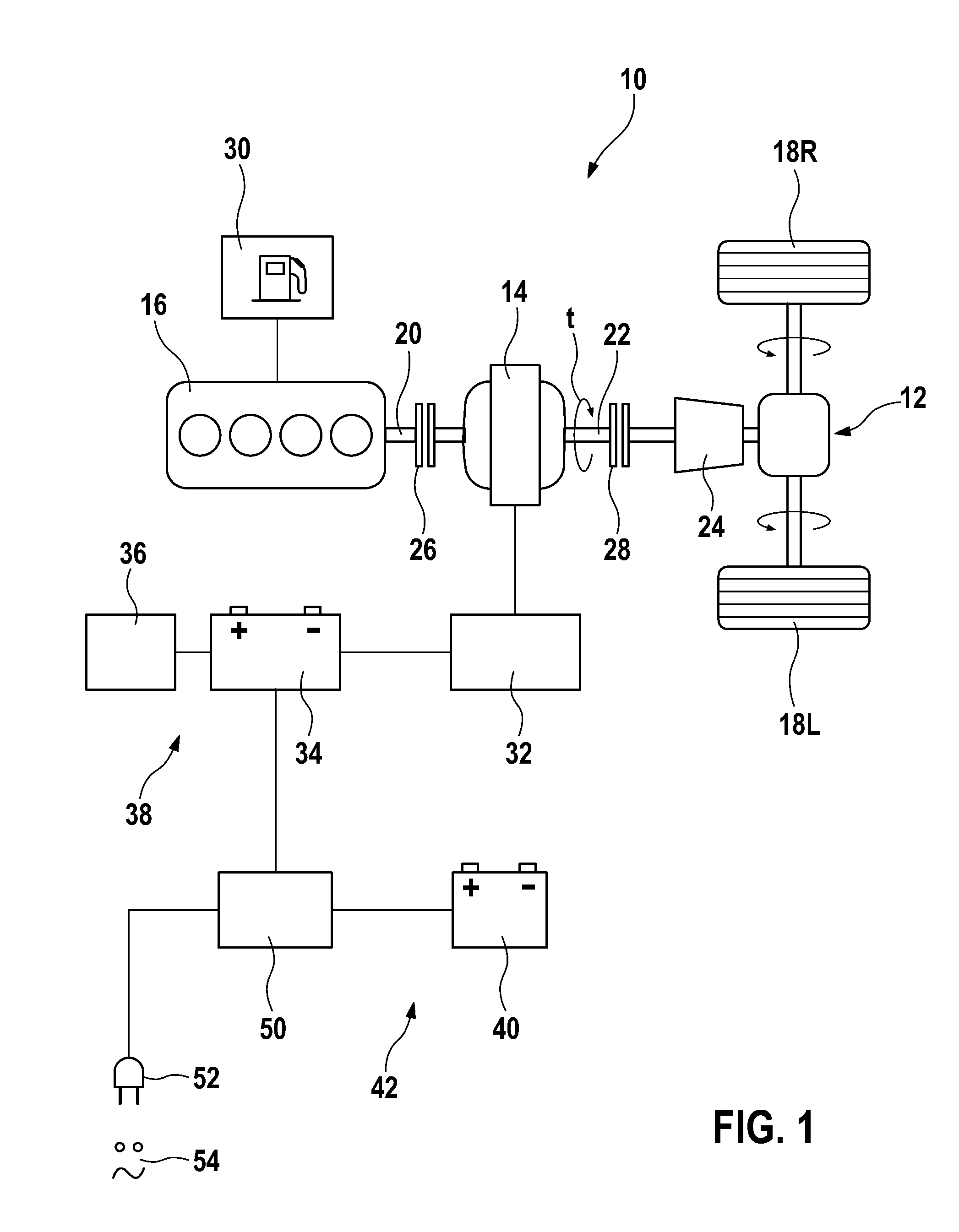
[0033]In FIG. 1, a motor vehicle is schematically depicted and denoted in total by the reference numeral 10. The motor vehicle 10 comprises a drive train 12 which, in the present case, includes an electrical machine 14 and an internal combustion engine 16 for providing driving power. The drive train 12 serves to propel the driven wheels 18 L, 18 R of the motor vehicle 10.

[0034]The internal combustion engine 16 is connected or can be connected via a crankshaft 20 to the electrical machine 14, wherein said internal combustion engine 16 and the electrical machine 14 provide a torque t at a driven shaft 22 which rotates at an adjustable rotational speed. The driven shaft 22 is connected or can be connected to a transmission unit 24 in order to transmit the torque t to the driven wheels 18R, 18L. The crankshaft 20 and the driven shaft 22 comprise in each case a clutch 26, 28 in the present case in order to connect the combustion engine 16 to the electrical machine 14 or the electrical ma...


PUM


Abstract

The invention relates to a converter circuit (50) for transferring electrical energy, in particular for application in a motor vehicle wiring system (38, 42), which converter circuit comprises an electromagnetic transfer unit (60) having three electromagnetic transfer members (62, 64, 66) that can be electromagnetically coupled to each other in order to transfer electromagnetic energy, wherein the first electromagnetic transfer member (62) is connected to a first bi-directional converter circuit that comprises a first voltage connection pole pair (80) for connecting an AC voltage source and/or sink (54), wherein the second electromagnetic transfer member (64) is connected to a rectifier converter circuit that is connected on the outlet side to an electrical energy store (88), and wherein the third electromagnetic transfer member (66) is connected to a second bi-directional converter circuit that comprises a second voltage pole pair (96) for connecting a DC voltage source and/or sink (98), and a control unit (100) that is connected to the first bi-directional converter circuit, the second bi-directional converter circuit and the rectifier converter circuit, in order to control the exchange of electrical energy between the AC voltage source and/or sink (54), the DC voltage source and/or sink (98) and/or the electrical energy store (88).

Description

BACKGROUND OF THE INVENTION[0001]The invention relates to a converter circuit for transferring electrical energy by means of an electromagnetic transfer unit.[0002]The invention further relates to a method for transferring electrical energy by means of a converter circuit of the type mentioned above.[0003]Finally the invention relates to an onboard voltage supply system of a motor vehicle comprising a converter circuit for transferring electrical energy of the type mentioned above.[0004]It is commonly known in the field of motor vehicle drive technology to use an electrical machine as a drive and to supply said electrical machine comprising a high-voltage battery with electrical energy. As a result, the high voltage battery is usually assigned to a high-voltage onboard supply system which has a voltage of more than 120 volts. It is furthermore commonly known to provide a low-voltage onboard supply system having a DC voltage of 12 volts in which at least one low-voltage supply batter...

Claims


Application Information

Patent Timeline
IPC IPC(8): B60L11/02B60L11/18B60L50/10
CPCB60L11/18B60L11/02H02M1/10B60L15/2045B60L2210/30B60L2210/46B60L2240/421B60L2240/423Y02T90/14H02J3/1842H02M3/33584Y02T10/70Y02T10/7072B60L53/14B60L50/14B60L50/16B60L58/20H02J2207/40H02J2310/48H02J7/02H02J2207/20Y02T10/64Y02T10/72H02J50/12H02J50/10Y02T90/12
Inventor GEYER, HANS
Owner ROBERT BOSCH GMBH
Why Eureka
Try Eureka