Animal Euthanasia Apparatus

Active Publication Date: 2014-08-21
BRODERICK CLIFFORD
View PDF12 Cites 5 Cited by
  • Summary
  • Abstract
  • Description
  • Claims
  • Application Information

AI Technical Summary

Benefits of technology

[0009]A device for euthanizing animals may include a specially constructed chamber with a door securable over an opening to the chamber cavity, being sealable on three sides against a door seal. The bottom of the opening of the chamber may have a threshold, over which a specially constructed cart/cage combination may be wheeled into the chamber cavity. The bottom of the door may therefore have an inflatable seal that may seal against the bottom of the door with respect to the threshold and the other door seal(s). A door latch is usable to secure the door in the closed position, and an electro-magnetic lock may additionally guard against unintentionally opening of the door during the process. A proximity switch may detect proper positioning of the cage/cart combination within the chamber, and one or more additional sensors may be used for verifying that the door is closed and locked.
[0010]A supply valve may control the flow of a euthanizing gas into the chamber, which may be heated by a heater to suitable temperatures. The supply valve may operate in conjunction with a fan and damper secured in a fresh air exhaust opening in the chamber that may simultaneously permit the outf

Problems solved by technology

Subsequently, the concentration of gas may be incre

Method used


Image

  • Animal Euthanasia Apparatus
  • Animal Euthanasia Apparatus
  • Animal Euthanasia Apparatus

Examples


Embodiment Construction

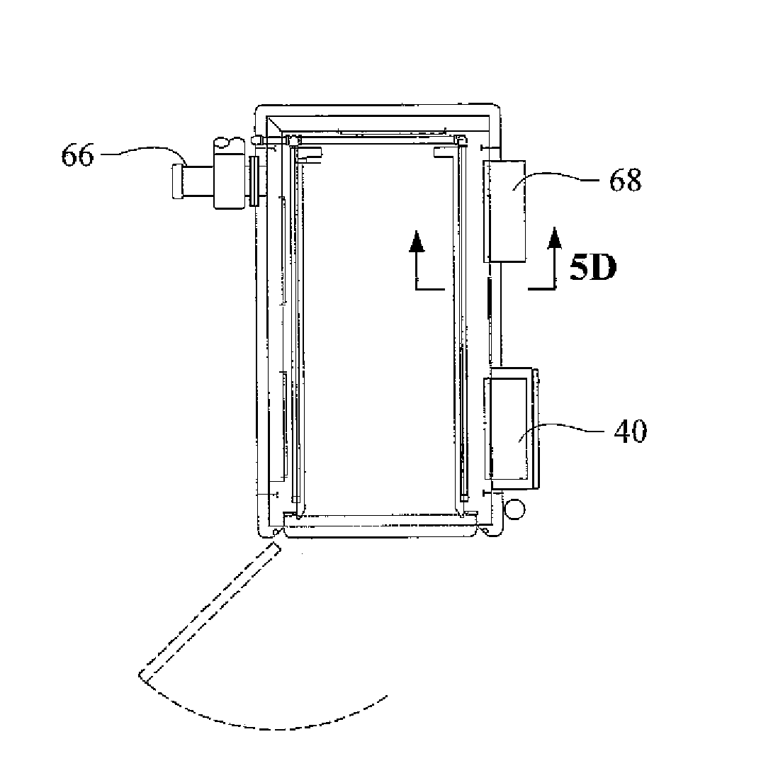
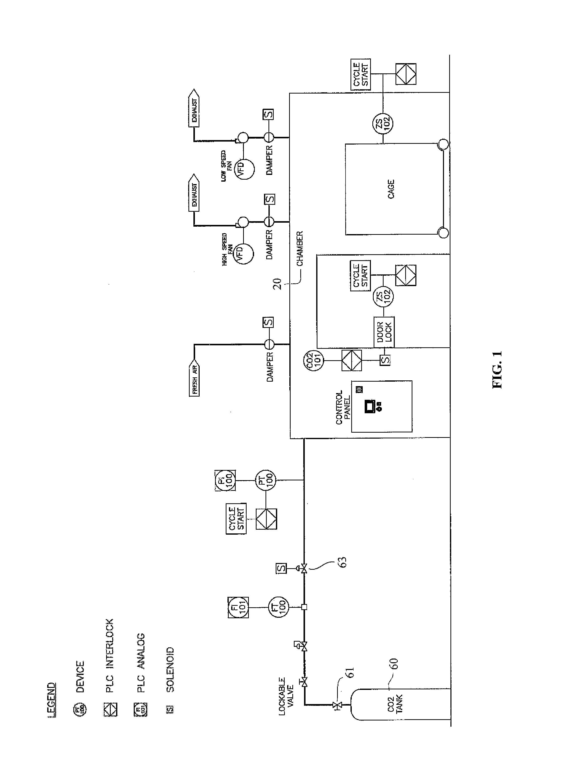
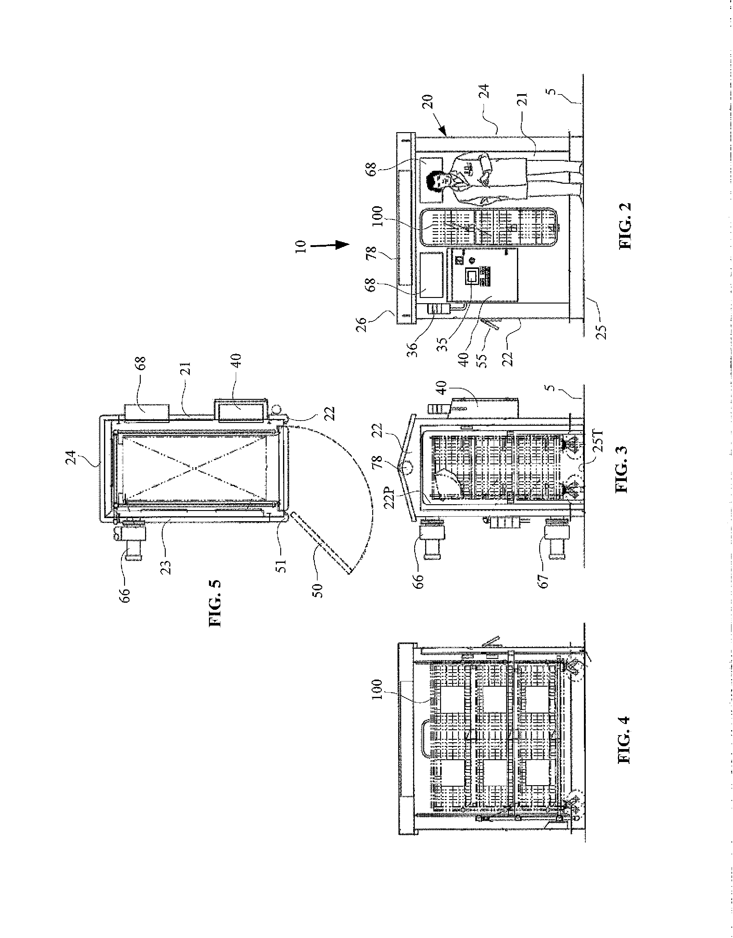
[0056]FIG. 1 shows a piping and instrumentation diagram for the improved animal euthanasia apparatus 10 of the current invention, while FIGS. 2-5 show orthogonal views of the device. As seen in FIG. 2 and in the enlarged view of FIG. 6, the device may preferably be constructed of sufficient dimensions to accommodate euthanizing of a single large animal—perhaps one being as large as, or even larger than a man, and may thus also accommodate simultaneous euthanizing of many smaller animals. Scaling of the invention to be larger or smaller is readily accomplished, as seen in the following discussion.

[0057]The improved animal euthanasia apparatus 10 may include a chamber 20. The chamber 20 may be formed in one of several different ways. The chamber may be formed of a plastic material that may be compatible with the euthanizing gas that is to be inhaled by the animals. For example, where the euthanizing gas is carbon dioxide (CO2), material compatibility is found with such plastics as: Ke...


PUM


Abstract

An animal euthanasia device includes a chamber with an opening through which a partitioned cage may be wheeled. A pivotally attached door seals the opening using fixed edge seals and an inflatable door threshold seal. A latch secures the door, once closed. After a sensor verifies door closure, an electro-magnetic lock prevents inadvertent door opening during the process, which may be automated using a programmable logic controller (PLC). The PLC coordinates actuation of a fan and damper within an air exhaust opening, a fan and a damper within an exhaust gas opening, and a damper within a fresh air inlet opening, and also triggers a solenoid valve that controls flow of euthanizing gas into the chamber. A keyed selector switch controls power to the device to initiate the automated process, which is monitored using oxygen sensors, and CO2 flow and pressure sensors, and is reported on a human machine interface.

Description

FIELD OF THE INVENTION[0001]The present invention relates to improvements in apparatus for euthanizing animals, and more particularly to apparatus which are capable of safely and effectively euthanizing a large animal or a large number of animals in an automated process.BACKGROUND OF THE INVENTION[0002]Many reasons arise which necessitate that the life of an animal must be terminated with minimal pain and distress. The reasons for euthanasia may include the diagnosis of an incurable disease such as cancer, painful medical conditions, broken limbs, exposure to the rabies virus, deterioration and impairment due to old age, and / or dissection and analysis of animals used in laboratory experimentation. There are a number of methods for performing euthanasia on various different animals, and many organizations promulgate standards for these procedures, including those of the American Veterinary Medical Association—The AVMA Guidelines on Euthanasia. These methods may generally be categoriz...

Claims


Application Information

Patent Timeline
IPC IPC(8): A22B3/00
CPCA22B3/005
Inventor BRODERICK, CLIFFORD
Owner BRODERICK CLIFFORD
Why Eureka
Try Eureka