Process to attach thermal stencils to a glass substrate and permanently etch a mark therein

a technology of thermal stencils and glass substrates, which is applied in the direction of paper/cardboard containers, manufacturing tools, instruments, etc., can solve the problems of glass cracking by an unskilled hand, high labor intensity, and extremely tedious, and achieve the effect of high resolution

Active Publication Date: 2014-08-21
HOLLOWAY MATTHEW R
View PDF5 Cites 5 Cited by
  • Summary
  • Abstract
  • Description
  • Claims
  • Application Information

AI Technical Summary

Benefits of technology

[0008]Industries including automotive, insurance and security companies, glass companies and consumer goods manufacturing companies have long seen and believed in the numerous benefits of permanently marking glass for anti-theft security, goods identification and recovery and also for logo and identification branding of glass parts. Herein presented is a process for producing a high resolution glass marking stencil, made from a bi-layer media consisting of a permeable paper tissue layer with another layer resistant to various glass etching compounds

Problems solved by technology

Previous methods of marking glass have ranged from stickers and non-permanent decals which are temporary and have otherwise, no theft deterrent or permanent identification properties, to engraving the glass surface with a carbide or diamond tipped bit in which requires a skilled craftsman's freehand to obtain an aesthetically pleasing result and which also has a drawback of the possibility of the glass cracking by an unskilled hand, to various methods of chemical etching to obtain a permanent etch mark and also using a focused laser light to mark glass items.
Methods utilizing a non-reactive coating to mask the glass, either by employing lead letters as suggested in the above mentioned patent or by hand with a non-reactive oily pen as described in U.S. Pat. No. 7,276,181 example 7, to create a “chemical” or “oil” mask wherein a glass etchant can then be applied to the non-coated glass are extremely tedious as each step requires a skilled craftsman and hand application can be time and labor intensive to effectively mask the negative image of the desired mark.
Using these protocols will not only result in a mask which may move upon the plane of the glass while wet when the etching compound is brushed on

Method used


Image

  • Process to attach thermal stencils to a glass substrate and permanently etch a mark therein
  • Process to attach thermal stencils to a glass substrate and permanently etch a mark therein
  • Process to attach thermal stencils to a glass substrate and permanently etch a mark therein

Examples


example 1

[0019]Preparation of an adhesive aqueous solution.

[0020]100 grams of raw polyvinyl alcohol (PVA) beads are mixed with 1.75 liters of hot water and agitated until the mixture is homogenized. This is let to cool. To this mixture 1.75 liters of denatured alcohol is mixed to form an adhesive aqueous solution.

[0021]Preparation of a glass etching compound.

[0022]To 1 gallon of boiling water, 250 grams of sucrose is added. Next 750 grams of ammonium biflouride flakes are added and agitated to make a consistent mixture that has a thick paste like viscosity which will not run when applied to vertical or curved surfaces.

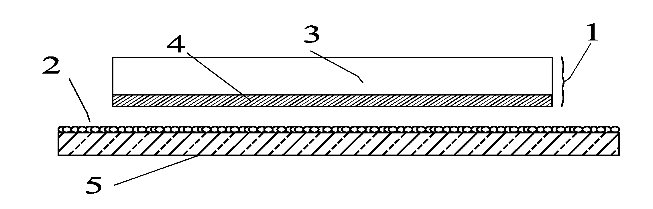
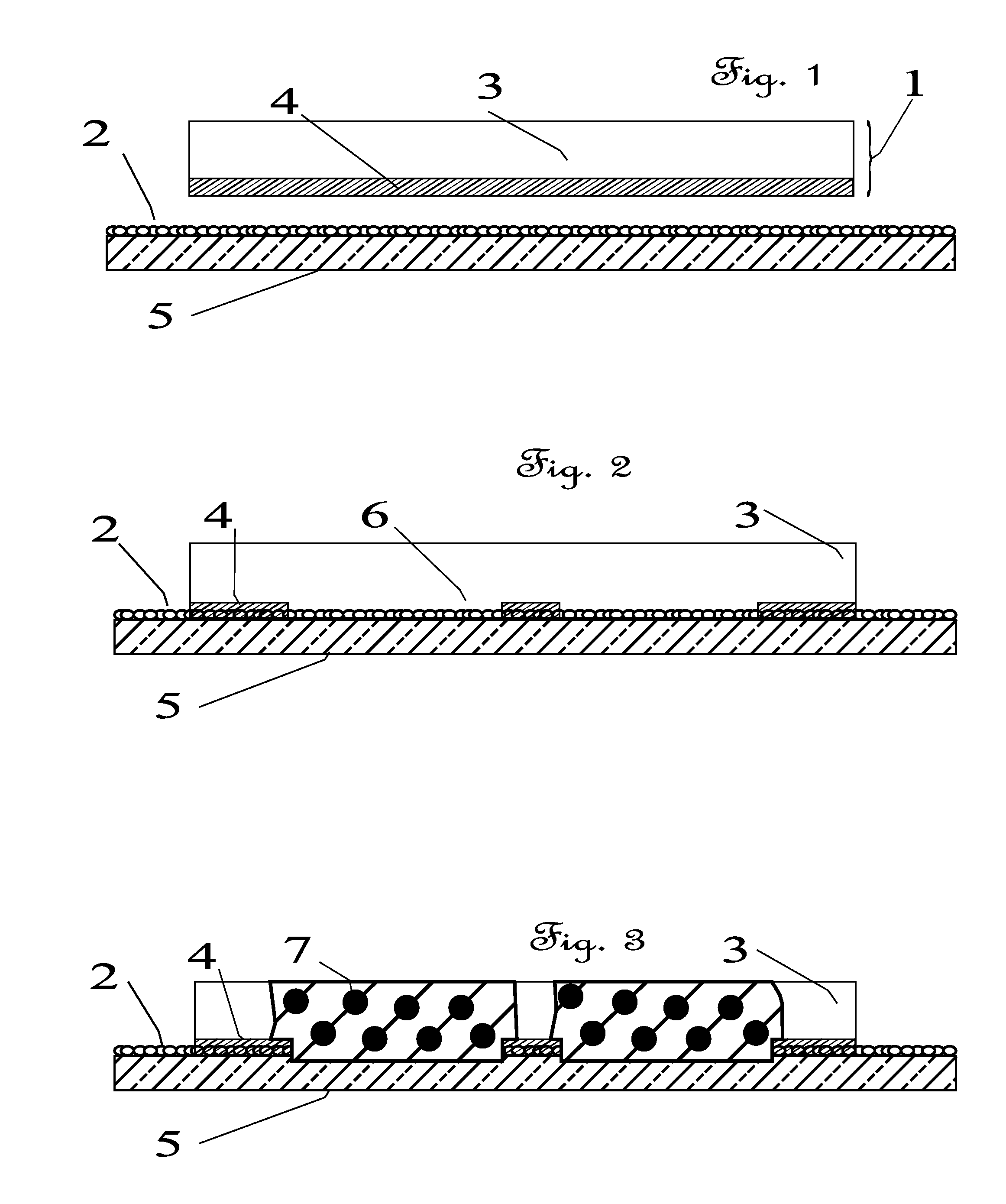
[0023]Preparation of the bi-layer stencil mask.

[0024]A bilayer thermal stencil media roll is loaded into a wireless networked direct thermal printer situated so the non-permeable to glass etchant, thermoplastic resin film resist layer of the stencil roll is in direct contact with the thermal print head. An image to be etched is designed and imputed by means of a wireless mobile...

example 2

[0027]Preparation of an adhesive aqueous solution.

[0028]8 U.S. tablespoons of high fructose corn syrup are added and mixed to 1.75 liters of ethanol and 1.75 liters of distilled water.

[0029]Preparation of a glass etching compound.

[0030]For this example, an ammonium biflouride solution prepackaged under the brand “Vari-Etch” cream and manufactured by His Glassworks from Asheville N.C., USA will be used.

[0031]Preparation of the bi-layer stencil mask.

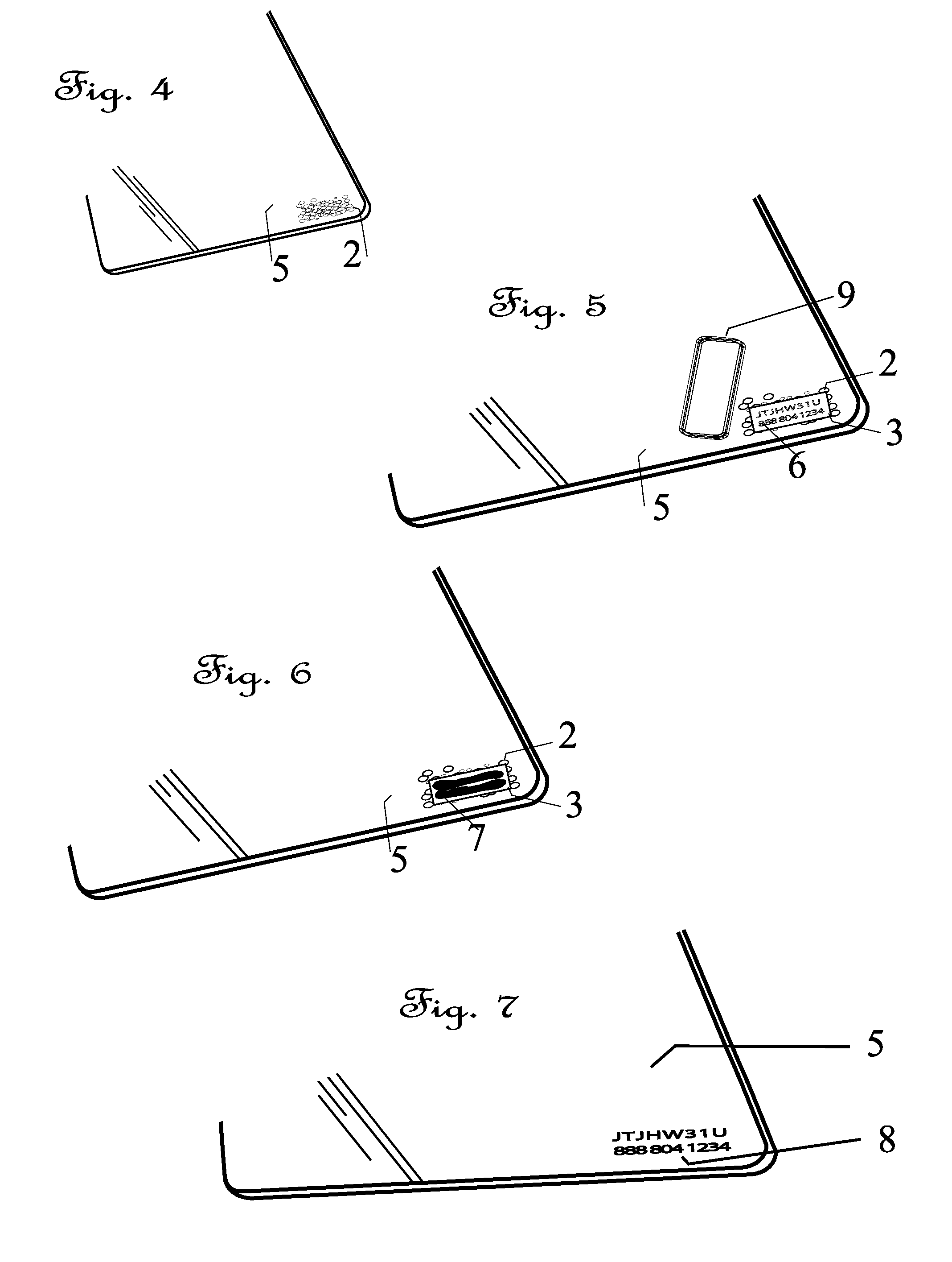
[0032]A bilayer thermal stencil media preloaded into a 1″ wide cassette cartridge as described in U.S. Pat. No. 5,771,803, is loaded into a compatible handheld thermal printer sold under the part number “P-Touch 1650” label maker from the Brother International brand and is situated so the non-permeable to glass etchant, thermoplastic resin film resist layer of the stencil paper is in direct contact with the integrated thermal print head. A vehicle identification number, or VIN, to be etched is imputed by means of the integrated thermal pri...


PUM

PropertyMeasurementUnit
Lengthaaaaaaaaaa
Timeaaaaaaaaaa
Adhesion strengthaaaaaaaaaa

Abstract

A high resolution stencil is produced by a thermal printer for the purposes of permanently etching glass for parts identification, tracking and labeling. An improved process to attach the stencil to the glass substrate is defined. An amended aqueous adhesive is used to bind the stencil so that it is in direct contact with the glass at all times and across the entire plane of the stencil and the adhesion is aided by use of a straight-edged tool to help evacuate any potential elements which may hinder the prescribed glass etching compound(s) from completing a clear and precise permanent mark.

Description

[0001]U.S. Patent Document(s):REFERENCES CITED95,617October 1869STRAUSS156 / 6634,585,514April 1986SCALLAN216 / 544,781,792November 1988HOGAN216 / 365,151,572September 1992JACK219 / 121.695,771,803June 1998TAKAMI101 / 128.217,276,181October 2007MIWA252 / 79.3FIELD OF THE INVENTION[0002]The invention pertains to the field of thermal marking stencils and permanently etching the surface of glass. Glass etching has been used for decades for the purposes of marking identifying marks, symbols, logos, images, serial numbers including vehicle identification numbers and strings of alphanumeric digits to the surface of individual glass parts or glass parts which partly constitute a whole good or item, including vehicles. Glass etching is especially useful in preventing or otherwise thwarting the theft of these goods and in identification of parts.BACKGROUND OF THE INVENTION[0003]Previous methods of marking glass have ranged from stickers and non-permanent decals which are temporary and have otherwise, no...

Claims


Application Information

Patent Timeline
IPC IPC(8): C03C15/00C09J129/04C09K13/08
CPCC03C15/00C09K13/08C09J129/04Y10T156/10Y10T428/24934
Inventor HOLLOWAY, MATTHEW R.
Owner HOLLOWAY MATTHEW R
Why Eureka
Try Eureka