Reversible fuel cell and reversible fuel cell system
- Summary
- Abstract
- Description
- Claims
- Application Information
AI Technical Summary
Benefits of technology
Problems solved by technology
Method used
Image

Examples
first embodiment
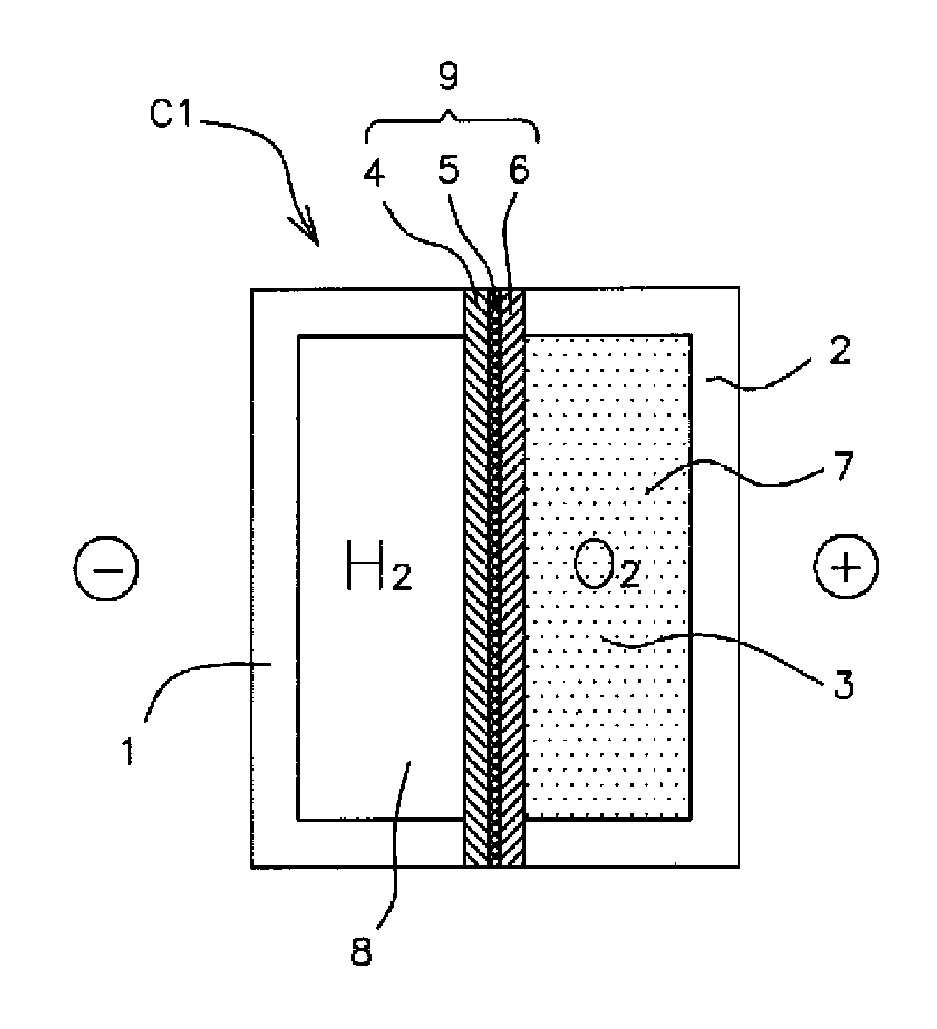
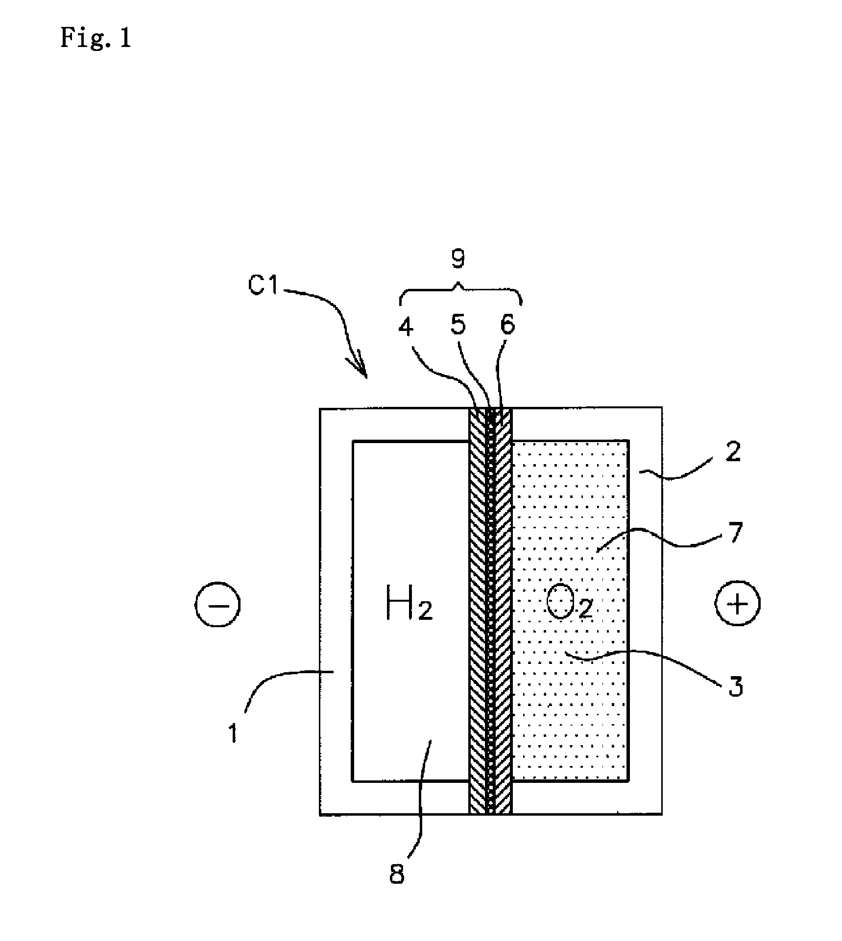
[0092]FIG. 1 is a section view schematically illustrating a structure of a reversible fuel cell C1 (hereinafter, simply referred to as a cell C1) according to a first embodiment, the cell C1 having a basic configuration of a fuel cell. The cell C1 utilizes chemical energy including hydrogen and oxygen by converting the chemical energy into electric energy. Further, the cell C1 is capable of storing the electric energy by converting the electric energy into chemical energy. The cell C1 includes, as main elements, a negative electrode 4, a positive electrode 6, an electrolyte 3, a negative electrode case 1 and a positive electrode case 2. The negative electrode 4 and the positive electrode 6 are opposed to each other with a separator 5 interposed therebetween. The negative electrode case 1 has a hydrogen storage chamber 8. The positive electrode case 2 has an oxygen storage chamber 7.
[0093]The negative electrode 4 contains, as a negative electrode active material, a hydrogen storage a...
second embodiment
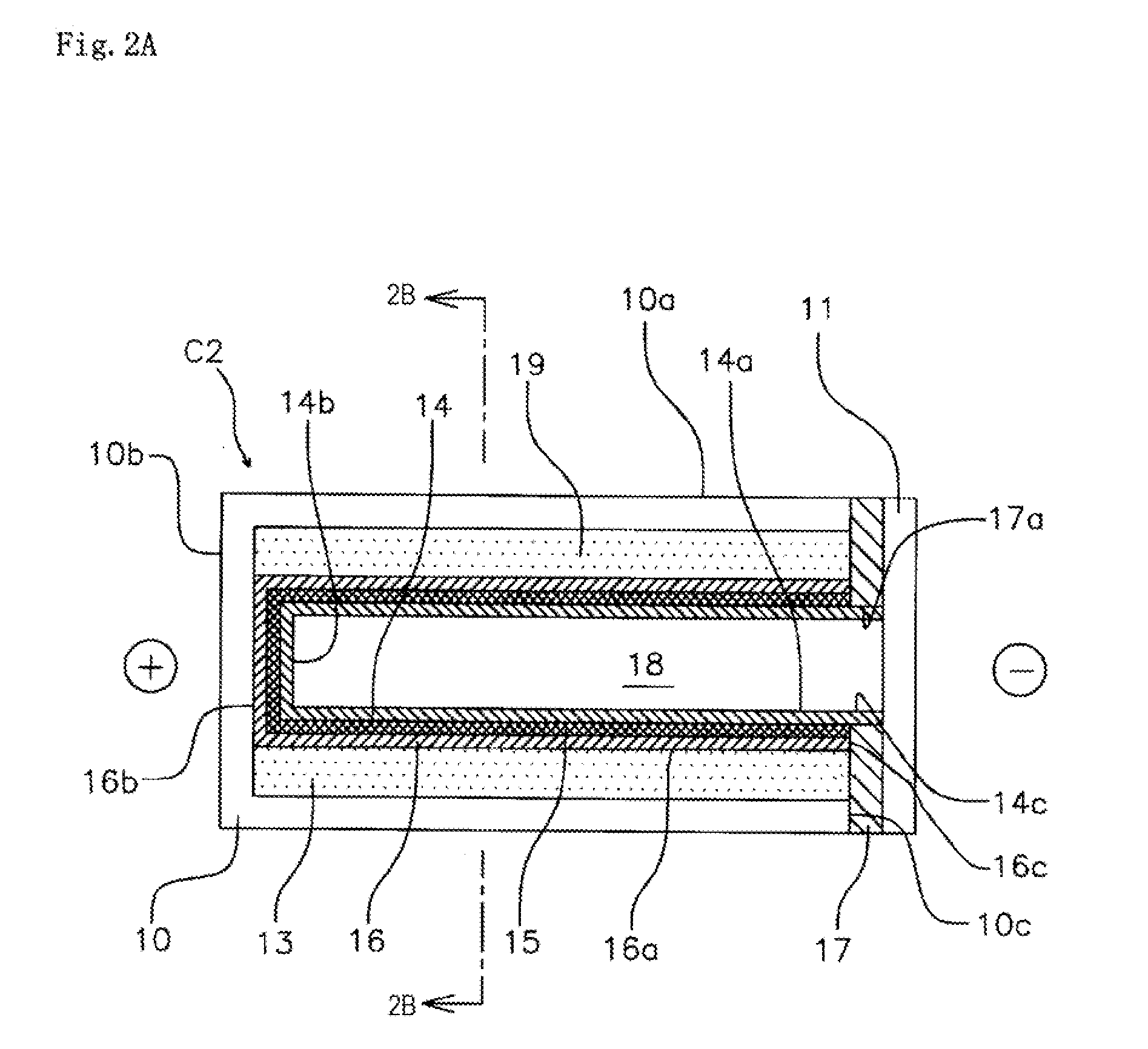
[0110]Next, description will be given of a cell C2 according to a second embodiment of this fuel cell. The cell C2 has a structure which is excellent in pressure-resistant performance and is easily handled. FIGS. 2A and 2B are section views each illustrating the structure of the cell C2. Herein, FIG. 2B is a section view taken along line D-D in FIG. 2A. The cell C2 has a similar basic configuration to that of the cell C1 according to the first embodiment illustrated in FIG. 1. As illustrated in FIG. 2A, however, the cell C2 has a tubular outer casing 10. Thus, the cell C2 exhibits excellent pressure-resistant performance and handling performance. Moreover, the cell C2 has an increased energy density and is easily handled. With regard to the cell C2 according to this embodiment, a negative electrode, a positive electrode, a separator and an electrolyte, which are basic elements of a battery, may have similar substances and structures to those of the cell C1 according to the first emb...
modification example of second embodiment
[0118]Next, description will be given of a cell C3 according to a modification example of the second embodiment of this fuel cell. FIG. 3 is a partial cutaway view illustrating a connection structure of the cell C3. The cell C3 corresponds to the cell C2 according to the second embodiment in which the outer structure is partially changed. Hereinafter, description will be mainly given of the change. The cell C3 has a negative electrode terminal 11 electrically connected to a negative electrode 14, at one end thereof in an axial direction (an axial direction of an outer casing 10). Moreover, the cell C3 has a positive electrode terminal corresponding to the outer casing 10 electrically connected to a positive electrode 16, at the other end thereof in the axial direction. As illustrated in FIG. 3, a projection 11d is formed on the center of the negative electrode terminal 11. Moreover, a bottom recess 10d is formed on the center of a bottom portion 10b of the outer casing 10. The proje...
PUM
 Abstract
Description
Claims
Application Information