Method for non-invasive mapping of myocardial electric activity

a myocardial electric activity and mapping technology, applied in the field of methods for mapping myocardial electric activity, can solve the problems of affecting the normal operation of the heart, and unable to reach the right atrium and the right ventricle without perforating the septum

Inactive Publication Date: 2014-08-21
KOREA RES INST OF STANDARDS & SCI
View PDF7 Cites 22 Cited by
  • Summary
  • Abstract
  • Description
  • Claims
  • Application Information

AI Technical Summary

Benefits of technology

[0017]In an embodiment of the present invention, mapping the degree of electric activity may use a minimum variance spatial filter, and the constraint condition may suppress the influence of correlated sources located at other regions to prevent interference generated from the correlated sources toward target sources to be estimated by the minimum variance spatial filter.

Problems solved by technology

Such a conduction abnormality develops atrial arrhythmia, tarchycardia, and heart failure that cause a stroke.
Moreover, myocardial conduction abnormality is the mechanism of ventricular fibrillation that causes sudden cardiac death resulting from cardiac arrest.
Since the EP test is invasive, it always involves the danger of surgery.
Although the catheter may be introduced into the left atrium and the left ventricle through the aorta, it cannot reach the right atrium and the right ventricle without perforating septum.
Likewise, although the catheter may be introduced into the right atrium and the right ventricle through the vena cava, it cannot reach the left atrium and the left ventricle without perforating septum.
Furthermore, a patient or doctors may be exposed to an excessive radiation such as X-ray during surgery may take several hours to locate the electrode at a correct position.
Especially, an additional magnetic position tracking system (e.g., Carto system) is needed for spatial mapping of myocardial electric activity, since a two-dimensional radiation image cannot provide spatial information on catheter position.
Moreover, the epicardial electrode array cannot be used in prognosis observation after surgery.
Therefore, the estimation of a weak current source or deep current source reveals significant errors.
As a result, the non-invasive current mapping has limitations in clinical application.

Method used


Image

  • Method for non-invasive mapping of myocardial electric activity
  • Method for non-invasive mapping of myocardial electric activity
  • Method for non-invasive mapping of myocardial electric activity

Examples


Embodiment Construction

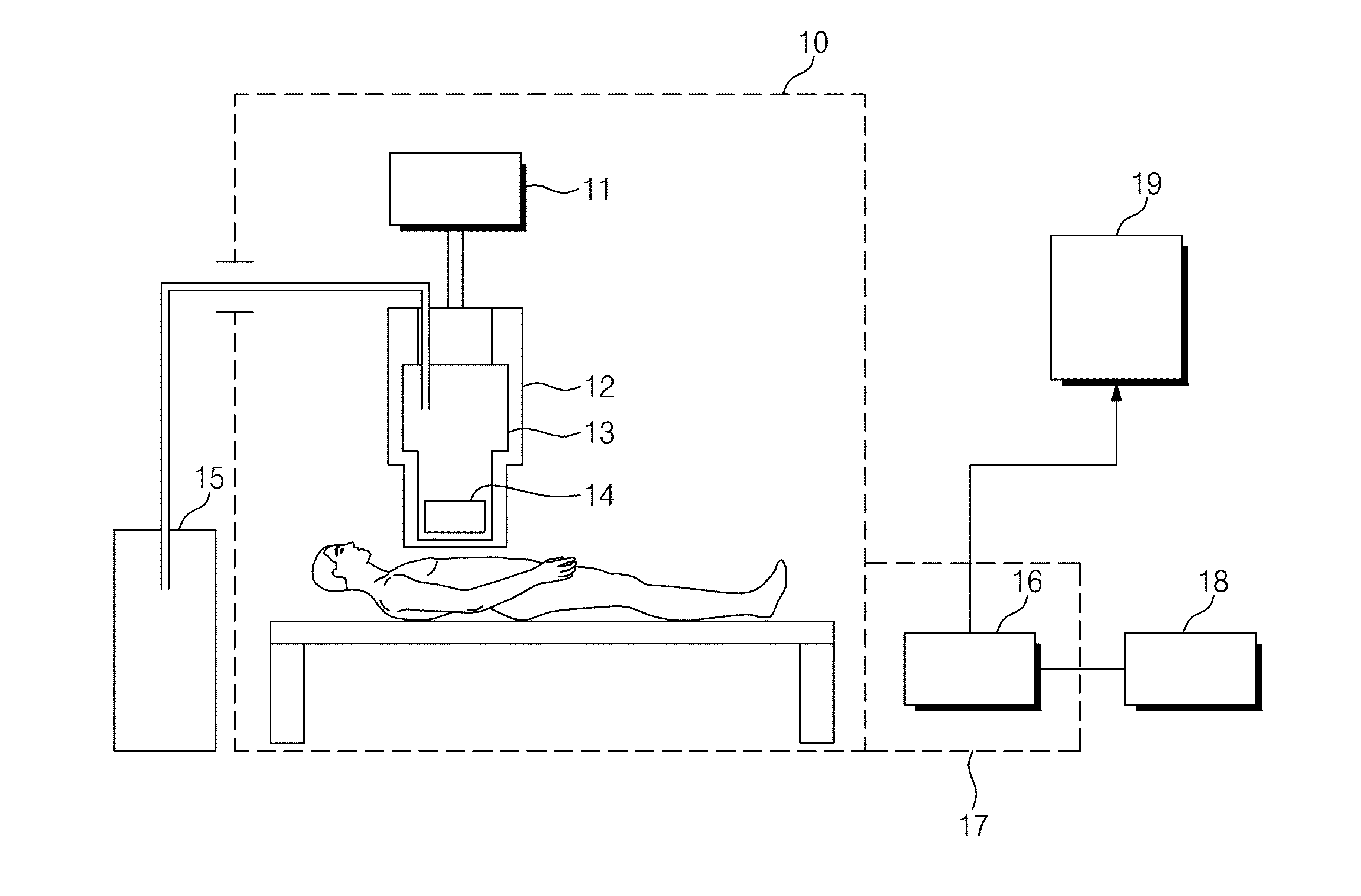
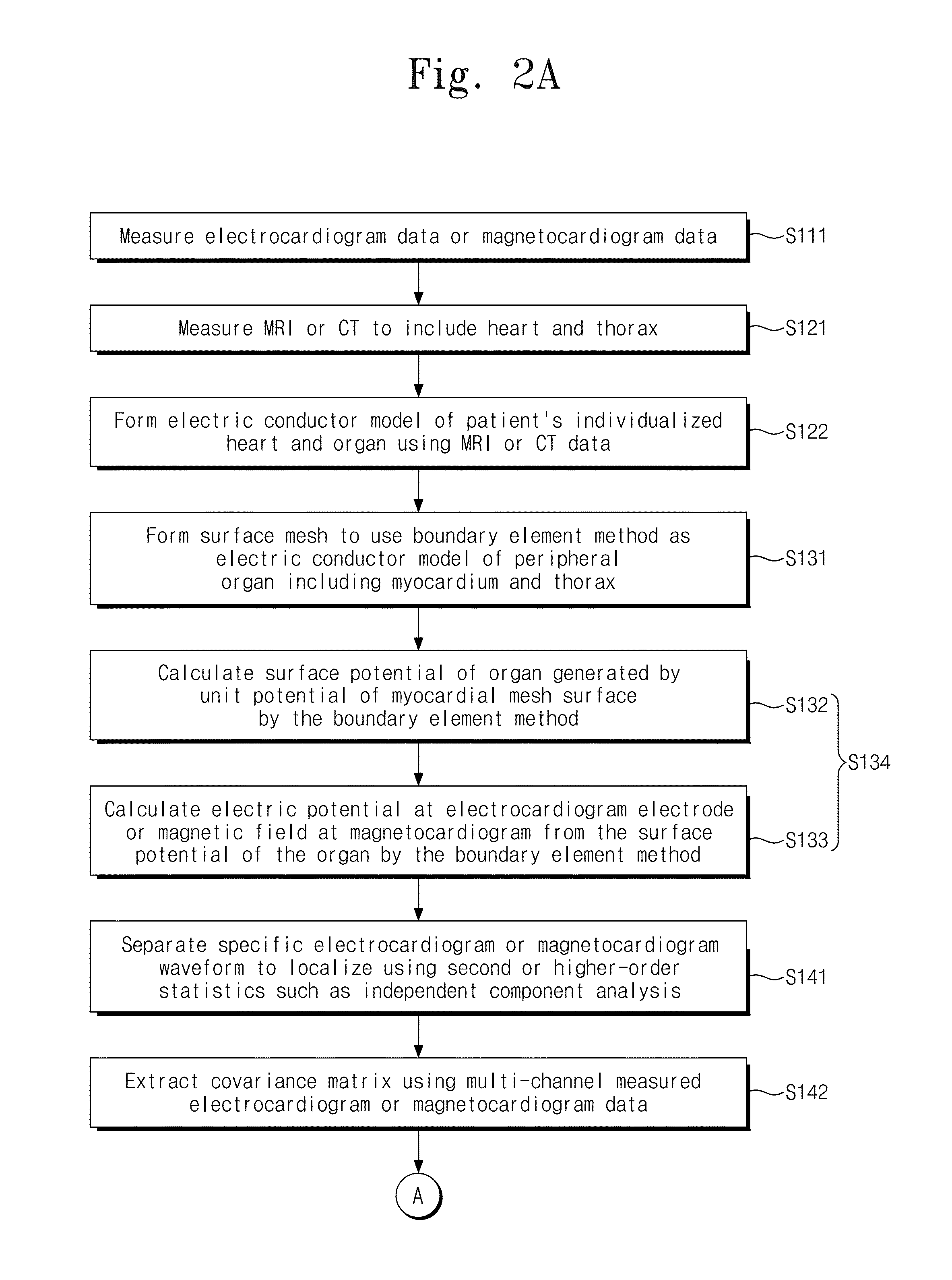
[0030]A method for mapping of myocardial electric activity according to an embodiment of the present invention calculates the position of the myocardial electric activity using data measured by multi-channel sensors. This method may be applied to both multi-channel electrocardiogram and multi-channel magnetocardiogram measurement data. For the convenience, only the magnetocardiogram measurement data will be described.

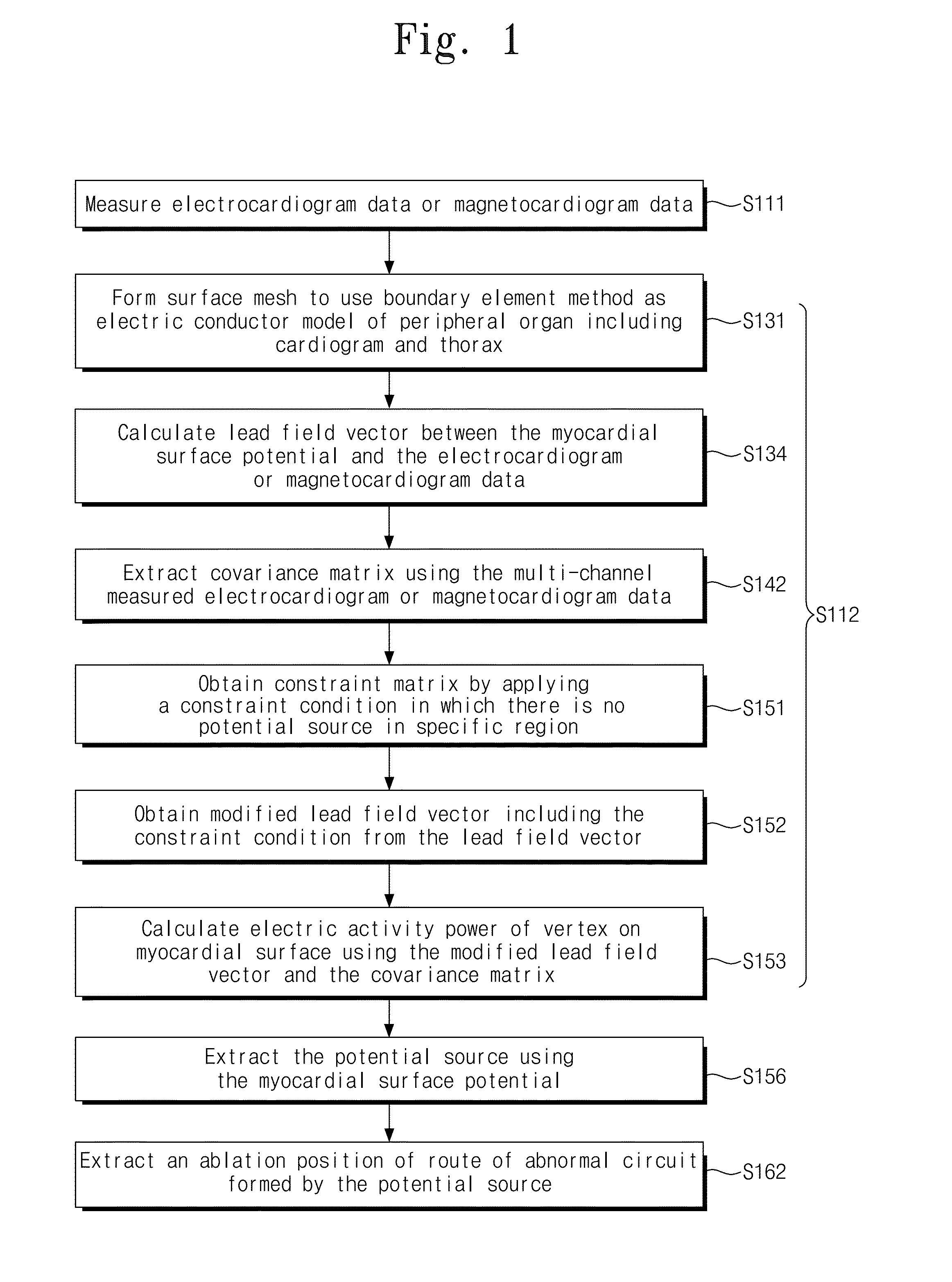
[0031]A beamforming method, which is a minimum variance spatial filter method, does not estimates a current source at a specific time but estimates a current source from a covariance matrix obtained from multi-channel data for a certain period of time. Thus, the beamforming method is suitable to localize a current source with periodicity such as reentry wave. However, the beamforming method contains intrinsic drawbacks. The first drawback is that the direction of current dipoles should be known before calculating source power in a beamformer based on an equivalent curre...


PUM


Abstract

A method for mapping of myocardial electric activity includes measuring electrocardiogram data or magnetocardiogram data and mapping the degree of electric activity of a myocardial surface using the electrocardiogram data or the magnetocardiogram data. A signal source of the electrocardiogram data or the magnetocardiogram data is a myocardial surface potential that is scalar quantity. The mapping uses a lead-field vector which represents the sensitivity between the myocardial surface potential and the electrocardiogram or magnetocardiogram data, and a modified lead-field vector which combines a constraint matrix with a constraint condition where no potential sources exist in a specific region.

Description

CROSS-REFERENCE TO RELATED APPLICATIONS[0001]This application is a continuation of and claims priority to PCT / KR2012 / 008425 filed on Oct. 16, 2012, which claims priority to Korea Patent Application No. 10-2011-0109926, filed on Oct. 26, 2011, the entirety of which is incorporated by reference herein.BACKGROUND[0002]1. Field of the Invention[0003]The present invention described herein generally relates to methods for mapping of myocardial electric activity and, more particularly, to a method for estimating a position of myocardial electric activity with periodicity, such as reentry wave or ectopic excitation, from multi-channel data measured by electrocardiogram or magnetocardiogram.[0004]2. Description of the Related Art[0005]Many heart diseases are caused by reentry excitation or ectopic excitation of myocardium. Such a conduction abnormality develops atrial arrhythmia, tarchycardia, and heart failure that cause a stroke. Moreover, myocardial conduction abnormality is the mechanism...

Claims


Application Information

Patent Timeline
Patent Type & Authority Applications(United States)
IPC IPC(8): A61B5/04A61B6/03A61B5/055
CPCA61B5/04011A61B6/03A61B5/055A61B5/243A61B5/316A61B5/318G16H50/50G16Z99/00A61B5/0522A61B5/341
Inventor KIM, KIWOONGKWON, HYUKCHANLEE, YONG-HOYU, KWON-KYUKIM, JIN-MOK
Owner KOREA RES INST OF STANDARDS & SCI
Why Eureka
Try Eureka