Data Transmitter, Data Receiver, and Frame Synchronization Method

a frame synchronization and data transmitter technology, applied in the field of communication, can solve the problems of short average time for occurrence of frame loss, inability to implement fec decoding at the physical layer, and inapplicability of fec decoding at the medium access control layer in the prior art, so as to reduce additional overhead, improve usage efficiency of training sequence, and achieve the effect of not increasing system line ra

Inactive Publication Date: 2014-08-21
HUAWEI TECH CO LTD
View PDF19 Cites 10 Cited by
  • Summary
  • Abstract
  • Description
  • Claims
  • Application Information

AI Technical Summary

Benefits of technology

[0015]According to the technical solutions, a training sequence is inserted into an FEC code word, and the training sequence may be used to implement frame synchronization for the FEC code word. A training sequence is originally used in the prior art to assist in channel equalization and the like, and in the embodiments of the present invention, the originally existing training sequence is used to perform frame synchronization. In this way, no additional FEC frame header needs to be inserted. Therefore, an additional overhead may be reduced, the usage efficiency of the training sequence may be improved, and a system line rate will not increase.

Problems solved by technology

If FEC decoding is processed at the physical layer, a manner of performing FEC decoding by searching for frame header information at the medium access control layer in the prior art is no longer applicable and cannot implement FEC decoding at the physical layer.
However, if an OTU frame alignment mechanism is used, an average time for occurrence of frame loss is short, and the system is unstable.
In a case where the FEC decoding is implemented at the physical layer, an FEC frame header needs to be inserted at the transmit end, which will occupy an additional overhead, resulting in an increase in a system line rate.
Searching for a frame header to perform frame alignment is still required before FEC decoding at the receive end, and therefore a high-throughput system still requires a large amount of resources.

Method used


Image

  • Data Transmitter, Data Receiver, and Frame Synchronization Method
  • Data Transmitter, Data Receiver, and Frame Synchronization Method
  • Data Transmitter, Data Receiver, and Frame Synchronization Method

Examples


first embodiment

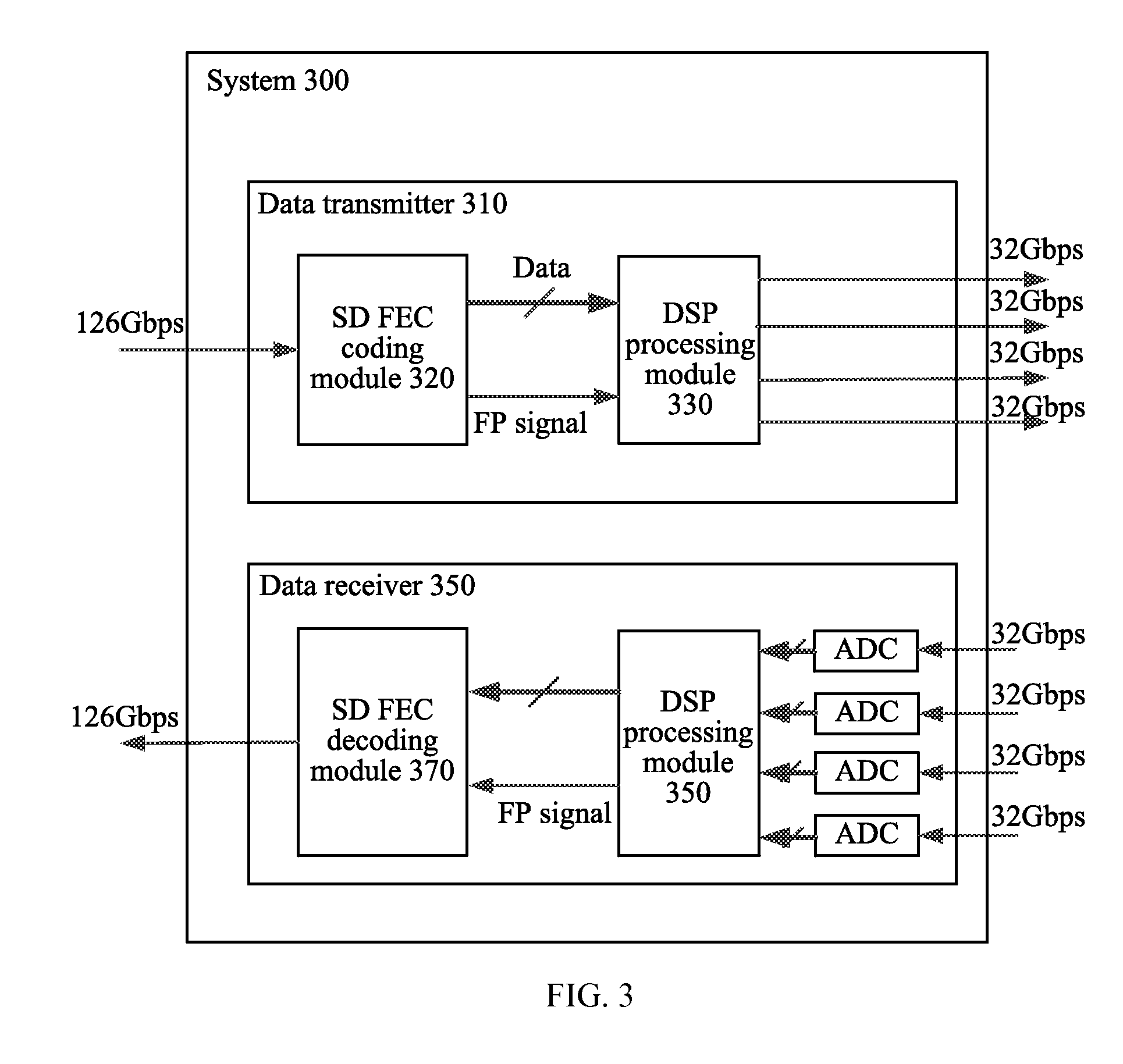
[0049]The following describes relevant operations of a transmitter and a receiver with reference to specific embodiments. First, a first embodiment about performing frame synchronization by using a training sequence is described with reference to FIG. 3 and FIG. 4.

[0050]In a system 300 including a data transmitter 310 and a data receiver 350 shown in FIG. 3, the system 300 uses coherent DP-QPSK (dual polarization quaternary phase shift keying) modulation, and 126 Gbps data is transmitted through four physical channels XI, XQ, YI, and YQ, where one training sequence cycle in the four physical channels corresponds to one SD FEC code word, so that the length of the SD FEC code word matches the length of the training sequence cycle. If the system 300 is a higher order modulation system, for example, DP-16QAM, one SD FEC code word is transmitted through eight physical channels, and one training sequence cycle in the eight physical channels corresponds to one SD FEC code word.

[0051]In the...

second embodiment

[0061]Next, a second embodiment in which frame synchronization is performed by using a training sequence is described with reference to FIG. 5.

[0062]The second embodiment is basically the same as the first embodiment, and differences are as follows. 1. The length of an FEC code word in the second embodiment is shorter and data in one training sequence cycle on each physical channel corresponds to a complete FEC code word, while the length of an FEC code word in the first embodiment is longer and data in the training sequence cycle in four physical channels corresponds to a complete FEC code word; and 2. A data receiver in the second embodiment performs FEC decoding on data of each physical channel separately, while a data receiver in the first embodiment performs FEC decoding after combining data of the four physical channels.

[0063]In a data transmitter 510 of a system 500, an SD FEC coding module 520 performs SD FEC coding on OTU4 data from an OTU framing module, and then sends an ...

third embodiment

[0066]A third embodiment in which frame synchronization is performed by using a training sequence is described below with reference to FIG. 6 and FIG. 7.

[0067]The third embodiment is basically the same as the first embodiment, and differences are as follows. 1. An SD FEC code word in the third embodiment is a long code and data of at least two training sequence cycles is inserted into one FEC code word, while data of one training sequence cycle is inserted into one FEC code word in the first embodiment. 2. One FEC code word in the third embodiment has multiple training sequence cycles and therefore an SD FEC decoding module needs to determine a frame header of an FEC code word according to the FP signal, while one FEC code word in the first embodiment has only one training sequence cycle and therefore the SD FEC decoding module directly uses the FP signal as an indication signal that indicates a frame header of the FEC code word.

[0068]In a data transmitter 610 of a system 600, an SD...


PUM


Abstract

Embodiments of the present invention provide a data transmitter, a data receiver, and a frame synchronization method. The data transmitter includes a coding module and a processing module. The coding module is configured to perform forward error correction FEC coding on sent data to obtain an FEC code word, and to output the FEC code word and an indication signal for indicating a boundary position of the FEC code word to the processing module. The processing module is configured to insert a training sequence into the FEC code word according to the indication signal, so that a data receiver determines the boundary position of the FEC code word according to the training sequence.

Description

[0001]This application is a continuation of International Application No. PCT / CN2011 / 081552, filed on Oct. 31, 2011, which is hereby incorporated by reference in its entirety.TECHNICAL FIELD[0002]The present invention relates to the communications field, and in particular, to a data transmitter, a data receiver, and a frame synchronization method in the communications field.BACKGROUND[0003]An optical transport network (OTN), based on wavelength division multiplexing technologies, of an optical layer organization network will be a next-generation backbone transport network. A single channel of an OTU4 (Optical channel Transport Unit 4) defined by the International Telecommunication Union-Telecommunication Standardization Sector transmits 112 Gbit data per second, and a forced out-of-band forward error correction (FEC) technology is used to improve the reliability of data transmission. The out-of-band FEC recommended by the OTU4 is a hard decision decoding FEC technology with a 7% ove...

Claims


Application Information

Patent Timeline
Patent Type & Authority Applications(United States)
IPC IPC(8): H04L1/00
CPCH04L1/0042H04L1/0047H04L1/0045H04L1/0041H04L25/0226H04L1/0057H04J3/0608H04J3/1652
Inventor YU, FANCHANG, DEYUANXIAO, ZHIYU
Owner HUAWEI TECH CO LTD
Why Eureka
Try Eureka