

Non-stick, pyrolytic coatings for heating devices
a technology of pyrolysis and heating devices, which is applied in the direction of heating types, lighting and heating apparatus, and domestic stoves or ranges
- Summary
- Abstract
- Description
- Claims
- Application Information
AI Technical Summary
Benefits of technology
Problems solved by technology
Method used
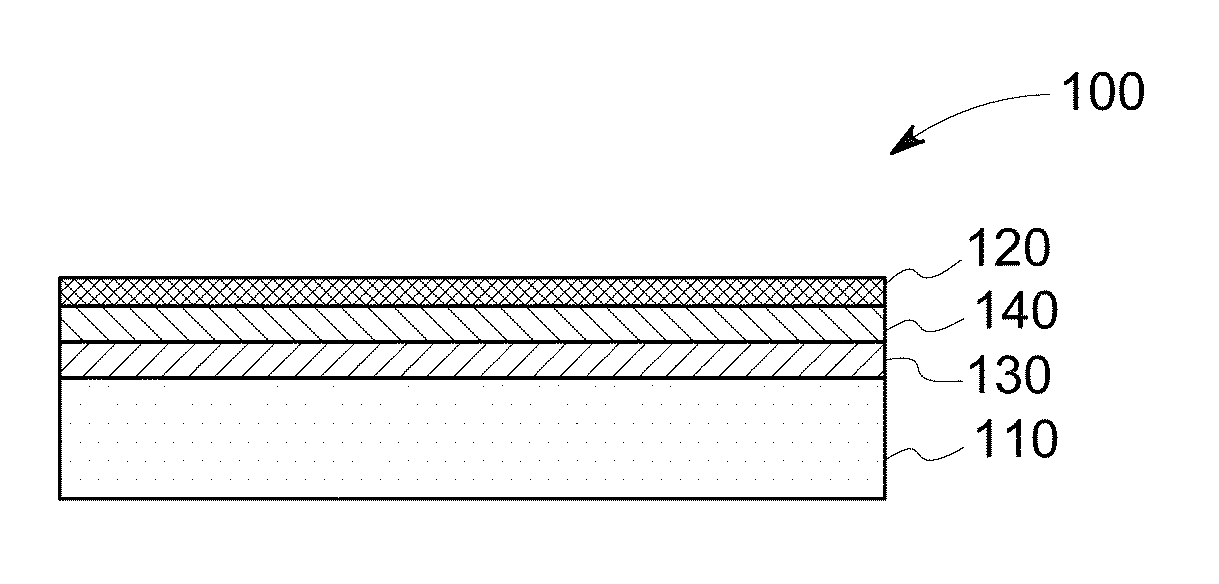
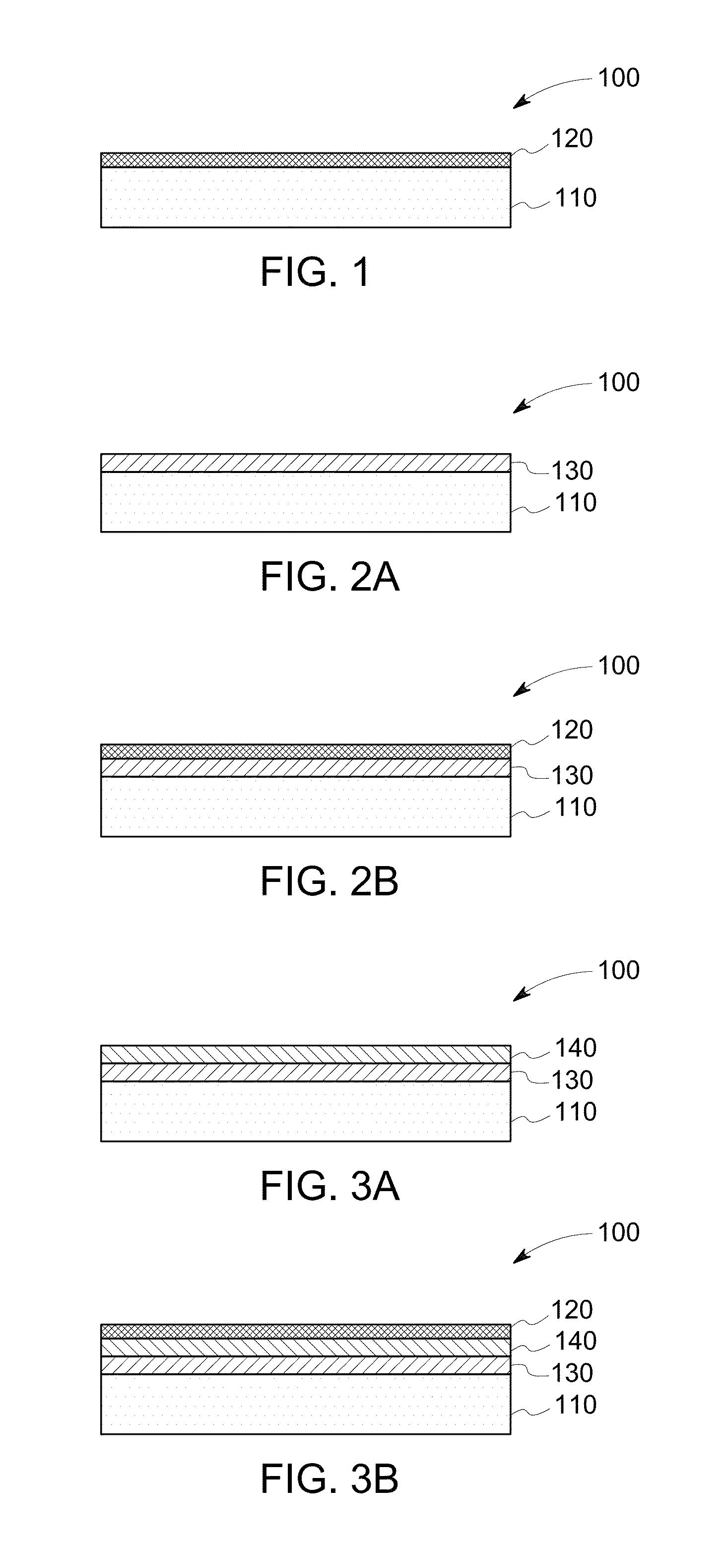
Image

Examples
example 1
Coating Including a Catalyst Material, and a Thermolon Binder
[0068]In this example, lanthanum strontium ferrite (LSF) catalyst was mixed with Thermolon coating composition in α-terpineol (at a concentration of up to 70 wt %) using a three-roll mill or a high speed centrifugal mixer to form a homogeneous paste. The catalyst paste was painted onto an oven panel section. The coated panel section was dried in an oven at 100° C. for 2 hours and then heat-treated at a temperature between 280 to 320° C. in air for 10-15 minutes.
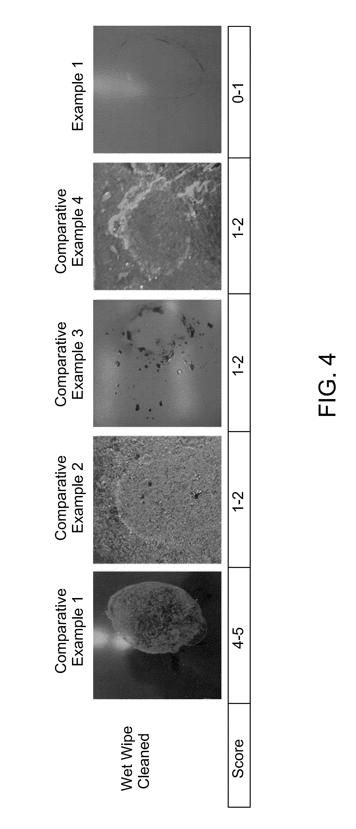
[0069]The coated panels of Comparative Examples 1-4 and Example 1 were evaluated to determine the cleanability effectiveness using AHAM stain testing procedure. After staining, the samples were then exposed to a self-clean cycle, which included heating the various stained samples in a furnace at 288° C. for 4 hours in air. A wet paper towel was then used to remove the food residue.
[0070]FIG. 4 and Table 1 summarize the cleanability results provided in Example 1 rela...
PUM
| Property | Measurement | Unit |
|---|---|---|
| Temperature | aaaaa | aaaaa |
| Temperature | aaaaa | aaaaa |
| Percent by mass | aaaaa | aaaaa |
Abstract
Description
Claims
Application Information