Check patentability & draft patents in minutes with Patsnap Eureka AI!

Method of manufacturing vehicle body side structure and vehicle body side structure

Active Publication Date: 2014-08-28
TOA IND CO LTD
View PDF2 Cites 19 Cited by
  • Summary
  • Abstract
  • Description
  • Claims
  • Application Information

AI Technical Summary

Benefits of technology

The invention relates to a method and structure for manufacturing a vehicle body side structure. The method involves using a first steel sheet to form an upper member, a second steel sheet with lower carbon content to form a lower member, and partially overlapping the upper and lower members with a blank member. The blank member is then spot welded to join the upper and lower members. The resulting structure has a lower strength of the lower member compared to the upper member. This method and structure provide enhanced safety and reduced weight of the vehicle body side structure.

Problems solved by technology

However, in the conventional method of manufacturing the pillar reinforcement 7, since the individual members are assembled and the spot welding is performed after the upper member 3a, the reinforcement member 3b and the lower member 3c are press formed as described above, there is a problem that the spot welding portion is limited.
This is because a spot welding portion is limited to a flat region of each of the members and the flat region is narrowed unavoidably since the peripheral ends of the individual members are bent in the case of spot welding after press forming.
Furthermore, in the case of spot welding after press forming, since the spot welded portion and the peripheral portion thereof are naturally cooled after the welding, there is a problem that the strength is decreased.

Method used


Image

  • Method of manufacturing vehicle body side structure and vehicle body side structure
  • Method of manufacturing vehicle body side structure and vehicle body side structure
  • Method of manufacturing vehicle body side structure and vehicle body side structure

Examples


Embodiment Construction

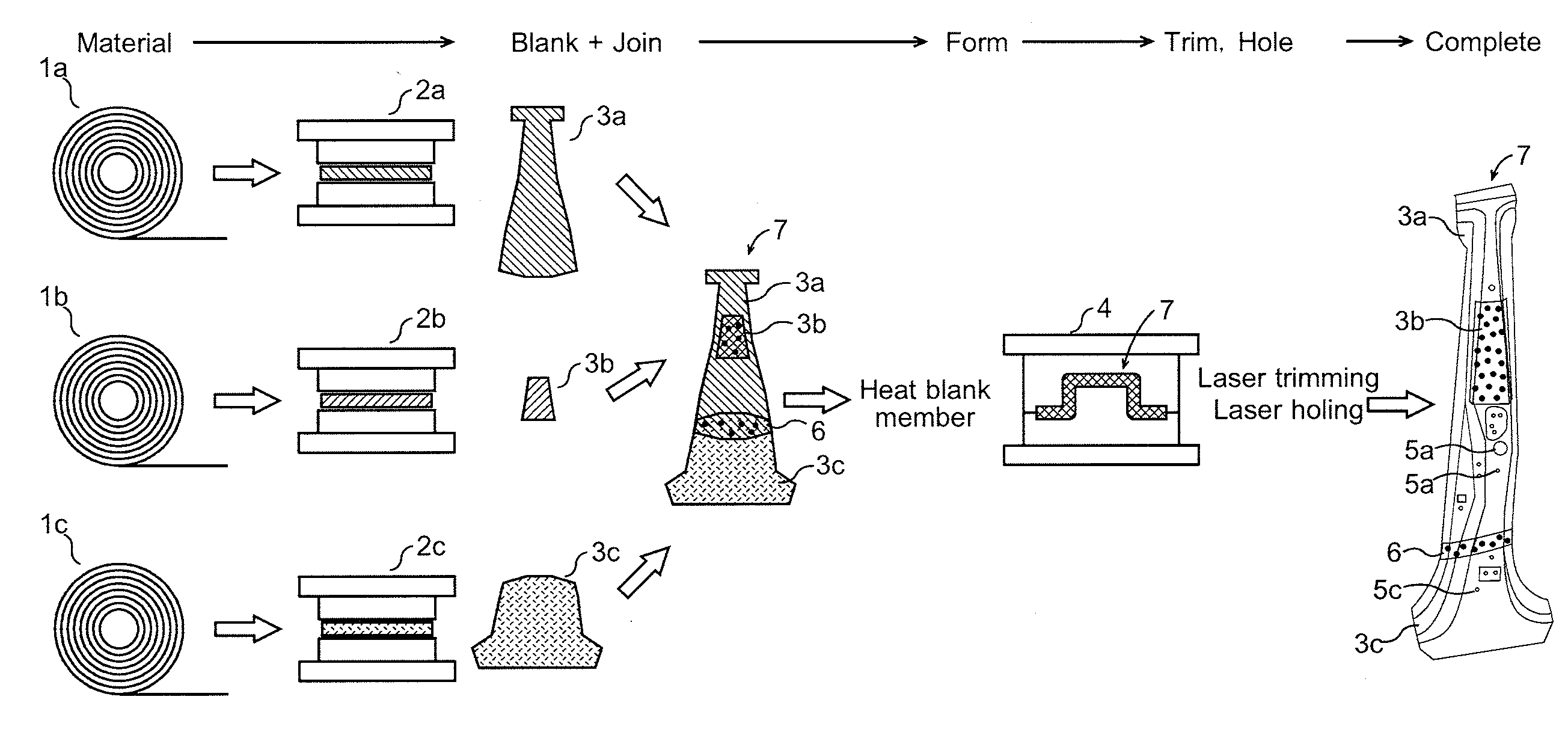
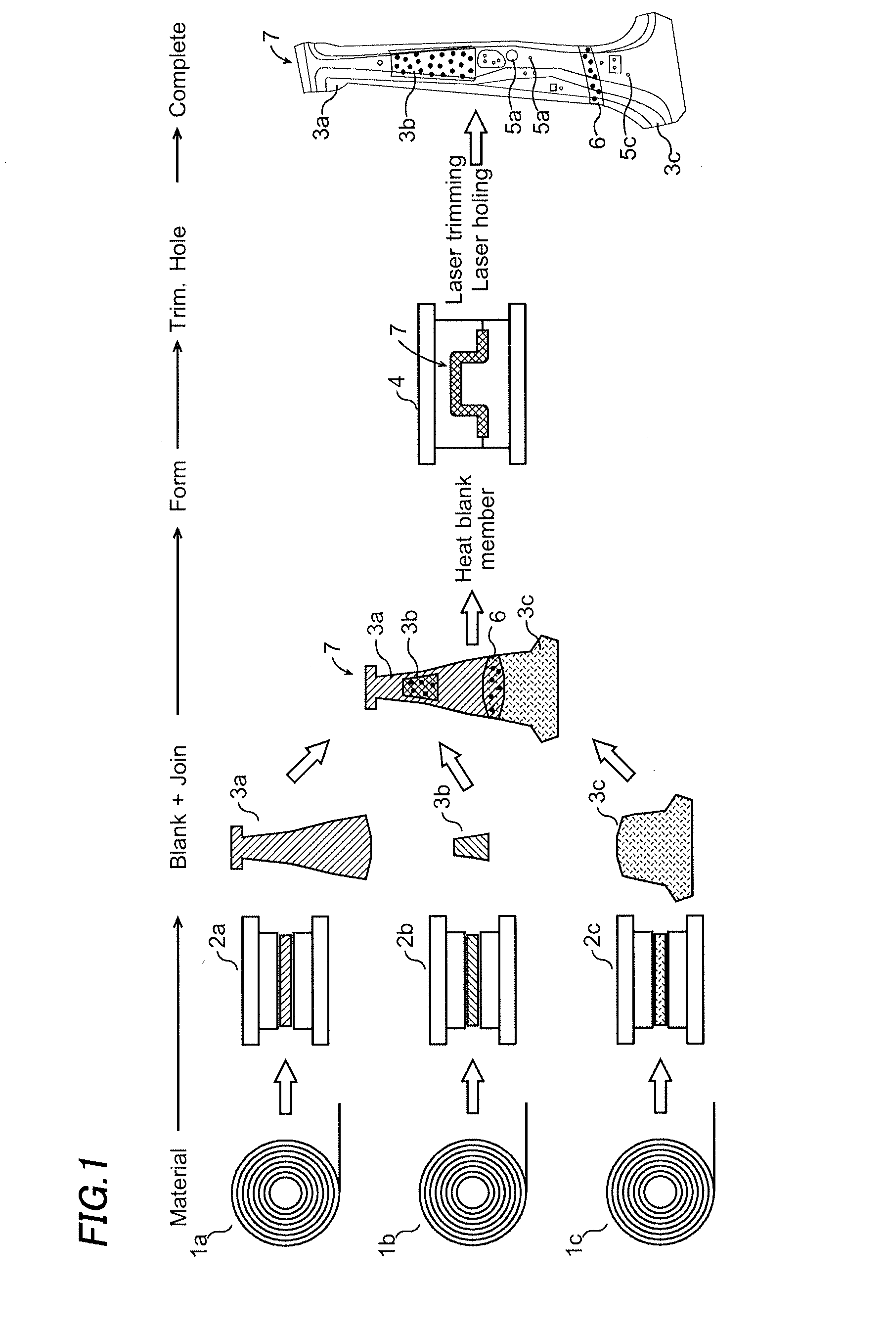
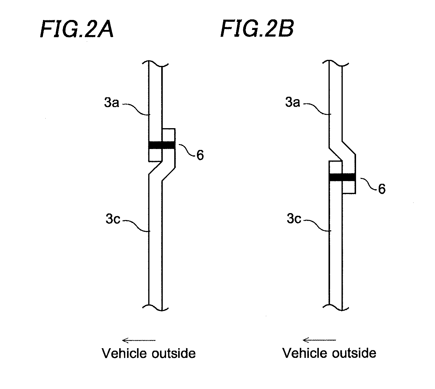
[0025]Hereafter, a method of manufacturing a vehicle body side structure in an embodiment of the invention will be described referring to FIGS. 1, 2A and 2B.

[0026]In the embodiment, an upper member 3a and a lower member 3c are joined each other through superposed portions 6 by spot welding to form a blank member, and this blank member is then hot press formed. It is generally known that the annealing effect when hot press forming is performed depends on the carbon content of a steel member.

[0027]In detail, in hot press forming, annealing reinforcement is made by heating a steel member to a transformation point or higher and transforming the metal structure of the steel member from austenite to martensite by quenching by a mold. At this time, as the carbon content of the steel member is higher, the transformation to martensite is more enhanced to increase the strength. On the other hand, when the carbon content of the steel member is low, the transformation to martensite is limited t...


PUM

PropertyMeasurementUnit
Fractionaaaaaaaaaa
Fractionaaaaaaaaaa
Temperatureaaaaaaaaaa

Abstract

First to third steel members are cut to form predetermined planar shapes using press machines and form an upper member, a reinforcement member and a lower member. The carbon content of the third steel member is set lower than the carbon content of the first and second steel members. The upper member, the reinforcement member and the lower member are then assembled. The reinforcement member is superposed on the upper member. The upper member and the lower member are partially superposed. The superposed portions of the upper member and the reinforcement member and the superposed portions of the upper member and the lower member are then respectively joined by spot welding to form a blank member. The spot welded blank member is then heated to a temperature of a transformation point or higher, and the blank member is hot press formed by one press machine.

Description

CROSS-REFERENCE OF THE INVENTION[0001]This application claims priority from Japanese Patent Application No. 2013-035652, filed Feb. 26, 2013, the content of which is incorporated herein by reference in its entirety.BACKGROUND OF THE INVENTION[0002]1. Field of the Invention[0003]The invention relates to a method of manufacturing a vehicle body side structure and a vehicle body side structure.[0004]2. Description of the Related Art[0005]A center pillar is disposed in the vertical direction of a vehicle body side portion, as a vehicle body side structure. The center pillar is configured so as to have a pillar reinforcement between a pillar outer panel and a pillar inner panel.[0006]In this vehicle body side structure, a strength change point is provided below the center portion of the center pillar in the vertical direction so that the strength of the member is higher in the upper portion from this strength change point and is lower in the lower portion.[0007]This vehicle body side str...

Claims


Application Information

Patent Timeline
IPC IPC(8): B62D65/02B62D25/04
CPCB62D65/02B62D25/04B21D22/208B21D35/007B62D29/007Y10T29/49622
Inventor YAJIMA, MASAKIKANAI, TAKASHI
Owner TOA IND CO LTD
Features
  • R&D
  • Intellectual Property
  • Life Sciences
  • Materials
  • Tech Scout
  • Unparalleled Data Quality
  • Higher Quality Content
  • 60% Fewer Hallucinations
Learn More