Magnet carrier

Active Publication Date: 2014-08-28
WITTENSTEIN SE
View PDF3 Cites 26 Cited by
  • Summary
  • Abstract
  • Description
  • Claims
  • Application Information

AI Technical Summary

Benefits of technology

[0024]Typically the plastic is injected or cast. Typical plastics can be thermoplastics or thermosetting plastics. Thermosetting plastics can be stiffer, tougher, or more resistant to chemicals. Thermoplastics can be more beneficial or simpler in manufacture. In addition fibres or other materials can be introduced into the plastics so as to improve the properties of the plastics. In embodiments with a rotor core the rotor core can be injected or cast together with the plastic between t

Problems solved by technology

However, plastic cages, or other parts cast in plastic for purposes of securing the positions of the magnets, have a small load capacity, so that rotational speeds are limited, or

Method used


Image

  • Magnet carrier
  • Magnet carrier
  • Magnet carrier

Examples


embodiment

OF EMBODIMENT

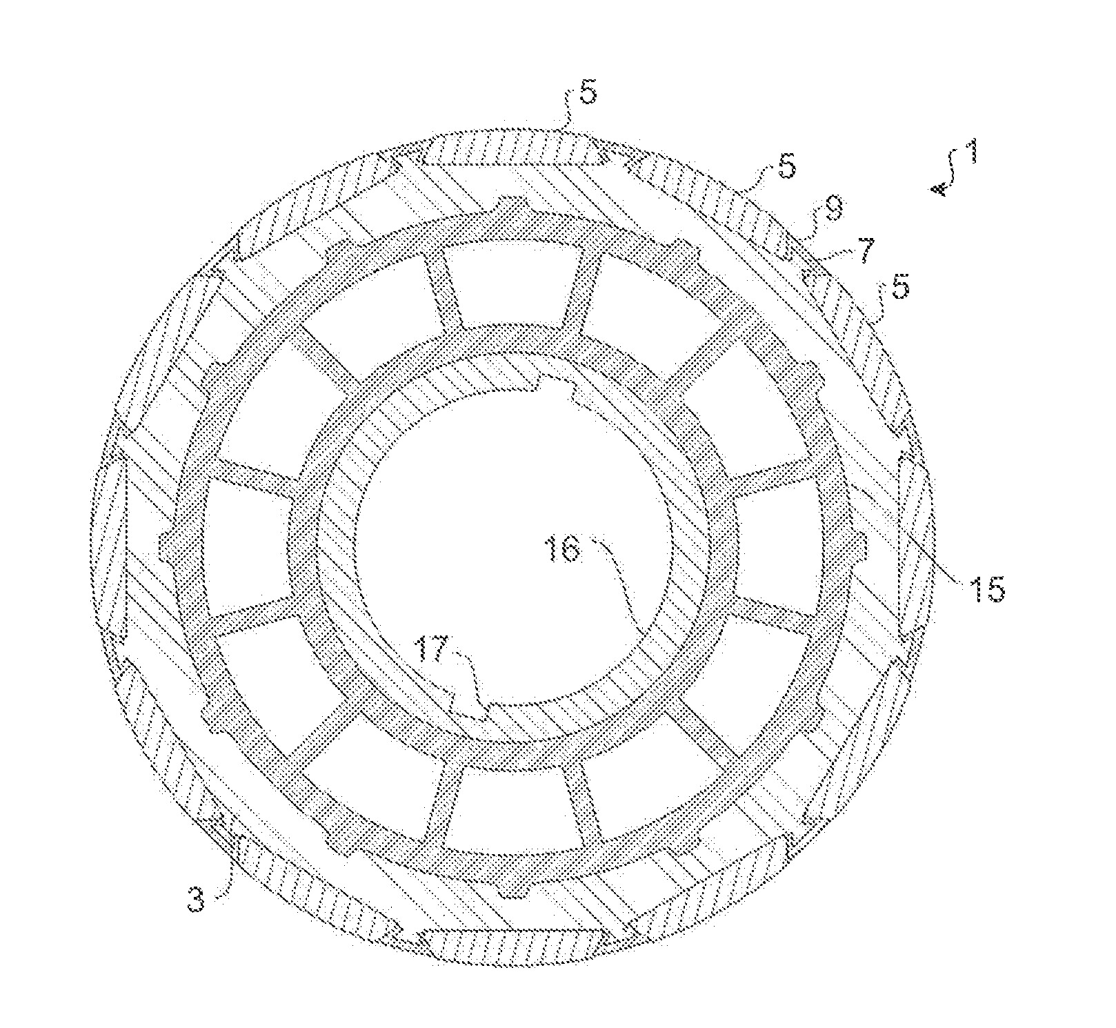
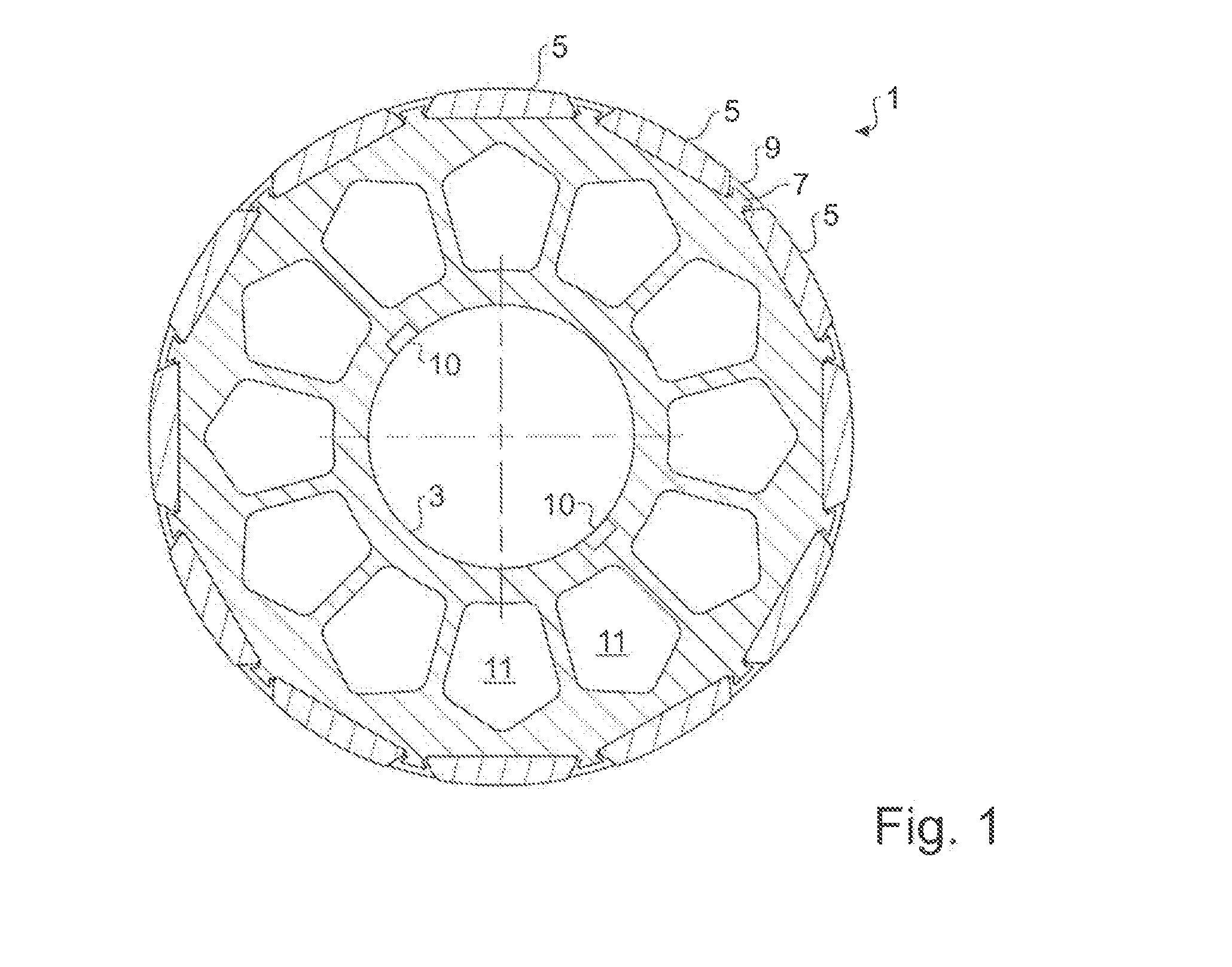
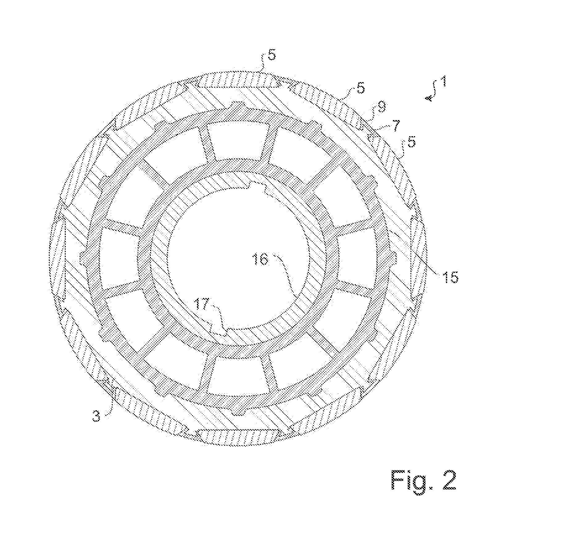
[0031]In FIG. 1 is shown a typical embodiment of a rotor 1, which is embodied as a permanent magnet rotor. The rotor 1 comprises a magnet carrier 3, on which magnets 5 are arranged. The magnets 5 are arranged on the magnet carrier 3 between respective protrusions 7. The protrusions 7 are integrally designed with the magnet carrier 3, or are permanently connected with the latter in a form fit or a material bond, for example, are welded on, or bonded on with adhesive. Between the magnets 5 and the protrusions 7 plastic 9 is arranged in each case, which completely encloses the protrusions 7 and which abuts against both the protrusions 7 and against partial surfaces of the magnets 5 in a precise fit. The plastic thus forms filler elements between the magnets 5.

[0032]Details in conjunction with the protrusions 7, the filler elements of plastic 9 and the magnets 5 are shown in FIG. 4, wherein, moreover, an alternative possible configuration of this region is shown in FIG. 5.

[...


PUM

PropertyMeasurementUnit
Angleaaaaaaaaaa
Electrical conductoraaaaaaaaaa
Widthaaaaaaaaaa

Abstract

A rotor, in particular a permanent magnet rotor, for an electrical machine, with a magnet carrier arranged concentrically with an axis of the rotor, wherein the magnet carrier has protrusions on its outer face, a number of magnets arranged on the outer face of the magnet carrier, which are arranged in the peripheral direction of the magnet carrier side-by-side and spaced apart from one another on the magnet carrier, wherein the magnets in each case are arranged between the protrusions, and plastic, which in each case is arranged between the magnets and at least partially encloses the protrusions.

Description

RELATED APPLICATIONS[0001]This application claims priority to German Patent Application No. 102013101957.9, filed Feb. 27, 2013, which is herein incorporated by reference.BACKGROUND[0002]1. Technical Field[0003]The invention relates to a rotor for an electrical machine and a manufacturing method for a rotor.[0004]2. Description of the Related Art[0005]From the prior art various permanent magnet rotors are of known art, wherein from the prior art a magnet carrier, on which magnets are arranged outboard is known. The magnets are, for example, held in their positions by means of plastic.[0006]Thus EP 1 748 533 B1 discloses a permanent magnet rotor with a plastic cage, into which magnets can be inserted in the axial direction,[0007]However, plastic cages, or other parts cast in plastic for purposes of securing the positions of the magnets, have a small load capacity, so that rotational speeds are limited, or large cross-sections are required so as to withstand the loads. The axial inser...

Claims


Application Information

Patent Timeline
IPC IPC(8): H02K1/28H02K15/02
CPCH02K1/28H02K15/02H02K1/278H02K1/30H02K7/04Y10T29/49012
Inventor HERZ, CHRISTIANGRONING, INGOLFDEMPEWOLF, KAY-HORST
Owner WITTENSTEIN SE
Why Eureka
Try Eureka