
Lead storage battery system

a lead storage battery and lead technology, applied in the field of lead storage battery system, can solve the problems of power quality degradation, global warming is a serious issue for all humankind, etc., and achieve the effects of reducing the cost required, less degradation, and increasing the longevity of lead storage batteries

Inactive Publication Date: 2014-08-28
HITACHI CHEM CO LTD
View PDF2 Cites 20 Cited by
  • Summary
  • Abstract
  • Description
  • Claims
  • Application Information

AI Technical Summary

Benefits of technology

The present invention can make lead storage batteries last longer without getting damaged. It can also save money by reducing the need for equalization charges. Additionally, it can make wind power generation storage systems last longer without needing maintenance. This helps manage operations better.

Problems solved by technology

Global warming is a serious issue for all humankind.
The wind power generation has a merit of not discharging carbon dioxide by utilizing a natural energy; however, there are concerns about power quality degradation as an adverse effect on a power system because the output of power generation is dependent on wind conditions and accordingly unstable.

Method used


Image

  • Lead storage battery system
  • Lead storage battery system
  • Lead storage battery system

Examples


example 1

[0130]FIG. 12 illustrates an operation of a lead storage battery system according to an example. The horizontal axis represents a time elapsed from an application of an equalization charge, while the vertical axis represents the SOC. The usable SOC range (an SOC tolerance) is from 30% to 90%.

[0131]In FIG. 12, the next equalization charge is conducted before the lower limit of the SOC variation reaches 30%. In addition, the equalization charge can be also conducted before the upper limit of the SOC variation reaches 90%.

[0132]This allows many of the lead storage batteries to be charged without reaching the sulfation region, thereby reducing the degradation of the lead storage batteries.

example 2

[0133]FIG. 13 illustrates an operation of a lead storage battery system according to an example in which the degradation level of the lead storage batteries is taken into account. The horizontal axis represents a time elapsed from an application of an equalization charge, while the vertical axis represents the SOC. The usable SOC range (the SOC tolerance) at the start of the operation is from 30% to 90%.

[0134]In FIG. 13, the lower limit of the SOC variation rises from 30% over time. On the other hand, the upper limit of the SOC variation declines from 90% over time. Even if the degradation of the lead storage batteries advances, the states of charge of the lead storage batteries are controlled so as to fall within the usable SOC range by performing the equalization charge.

[0135]This allows many of the lead storage batteries to be charged without reaching the sulfation region, thereby reducing the degradation of the lead storage batteries.


PUM


Abstract

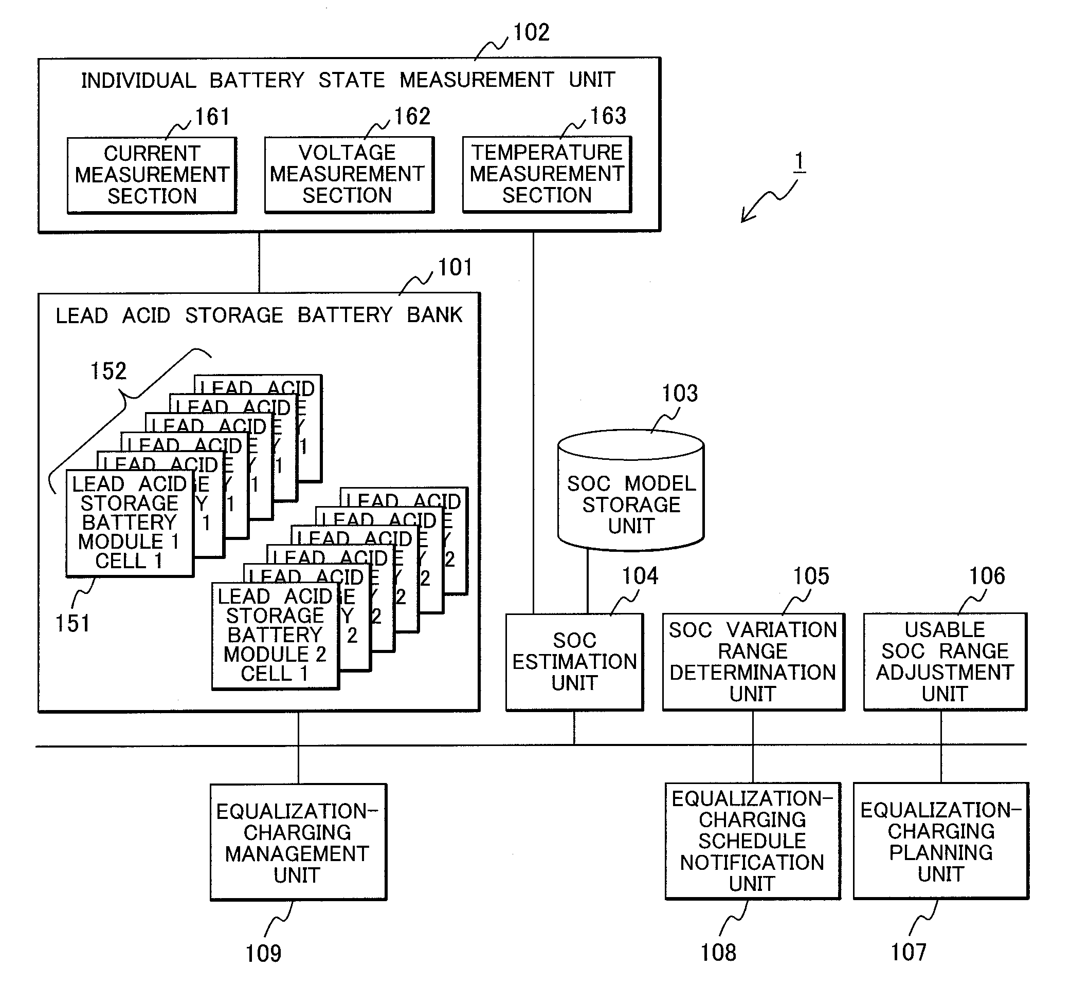
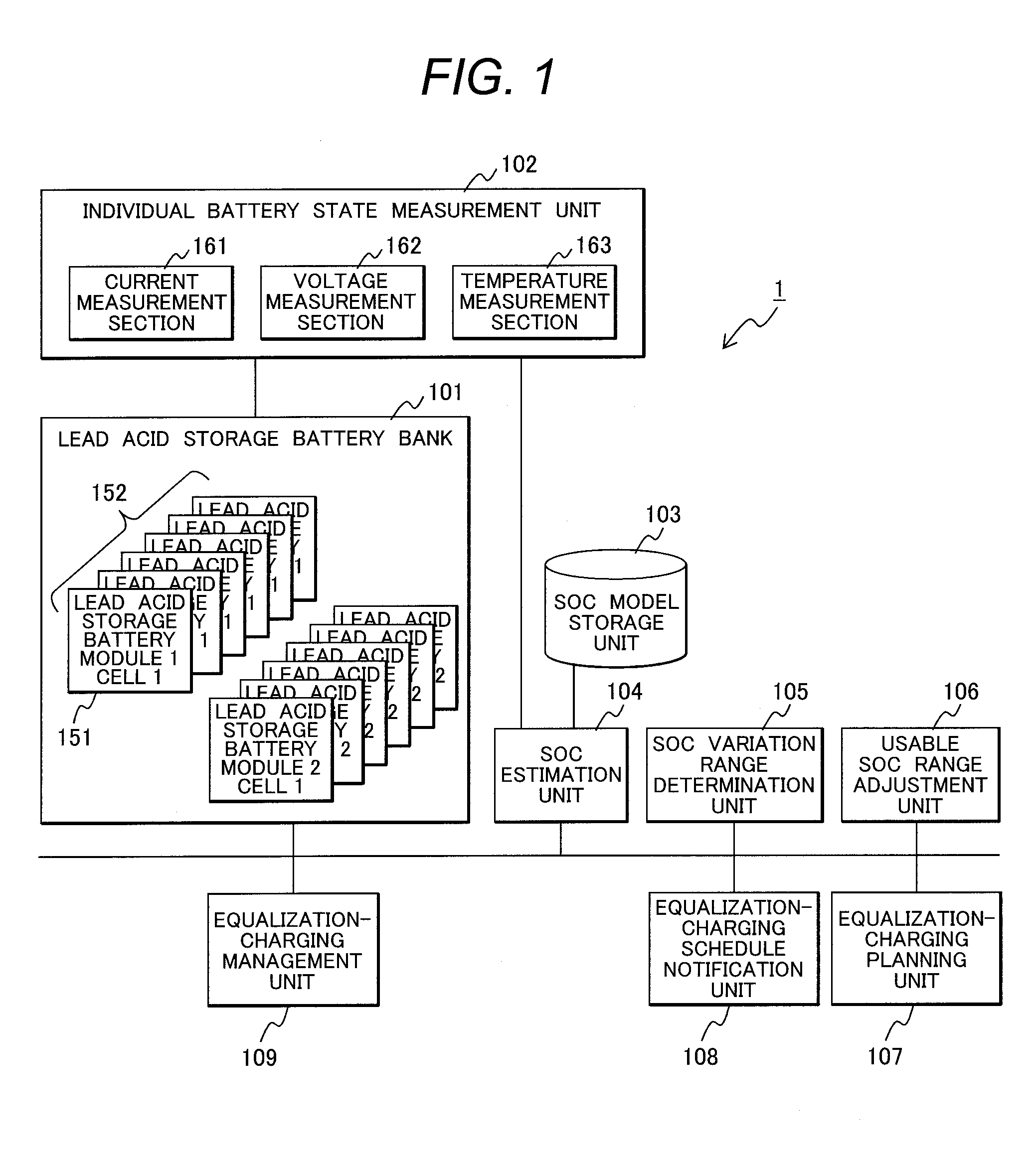
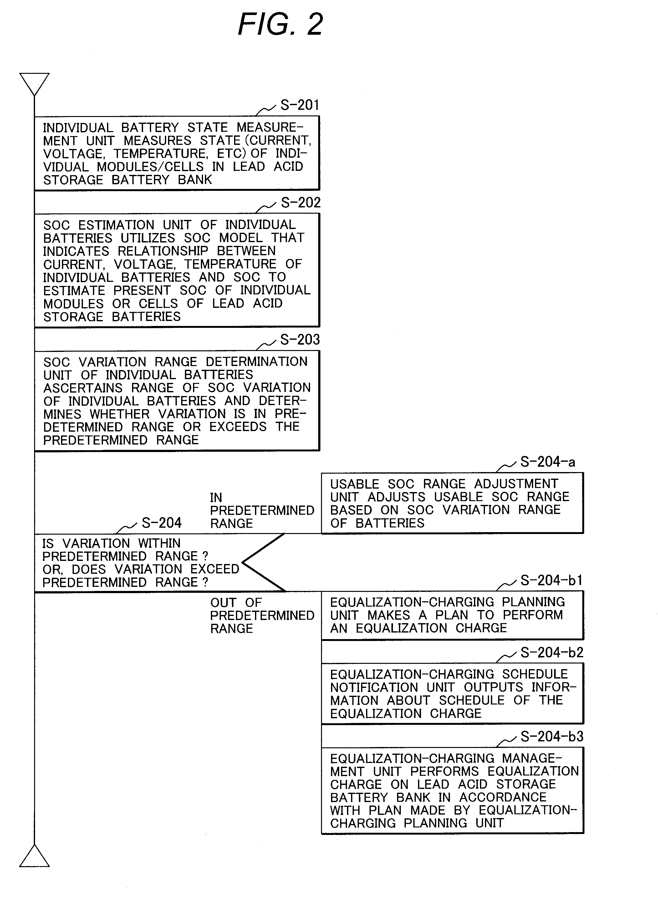
This invention reduces degradation of respective lead storage batteries making up a lead storage battery bank and extends the longevity of the lead storage batteries. A lead storage battery system includes an individual battery state measurement unit 102 that measures current, voltage, temperature etc. of individual lead storage batteries 151 or lead storage battery modules 152 making up a lead storage battery bank 101, a state-of-charge model storage unit 103 that accumulates state-of-charge models representing a correlation between the battery states and a state of charge, a state-of-charge estimation unit 104 that estimates individual states of charge of the respective lead storage batteries 151 or lead storage battery modules 152 from the state-of-charge models and the battery states, a state-of-charge variation range determination unit 105 that calculates a state-of-charge maximum value and a state-of-charge minimum value, and an equalization-charging management unit 109 that controls performance of an equalization charge on the lead storage battery bank 101. The equalization-charging management unit 109 performs the equalization charge so that the state-of-charge maximum value falls within a range lower than an overcharge region and the state-of-charge minimum value falls within a range higher than a sulfation region.

Description

TECHNICAL FIELD[0001]This invention relates to a lead storage battery system.BACKGROUND ART[0002]Global warming is a serious issue for all humankind. In order to delay and stop the progress of the warming, every country is trying to promote energy savings by building smart grids and promote large-scale introduction of natural energies that do not discharge carbon dioxide, such as photovoltaic power generation and wind power generation.[0003]The wind power generation has a merit of not discharging carbon dioxide by utilizing a natural energy; however, there are concerns about power quality degradation as an adverse effect on a power system because the output of power generation is dependent on wind conditions and accordingly unstable. For preventing such an adverse effect on the power system and effectively utilizing the energy, expectations are rising for wind power generation and storage systems using lead storage batteries or the like.[0004]A storage battery system used to reduce ...

Claims


Application Information

Patent Timeline
Patent Type & Authority Applications(United States)
IPC IPC(8): H02J7/00
CPCH02J7/0014H01M10/441H01M10/482H01M10/486H01M2010/4271G01R31/382G01R31/367G01R31/379G01R31/396H02J3/32H02J2300/28H02J3/381Y02E10/76Y02E60/10
Inventor ABE, KEIKOINOUE, HIDEKISAWA, TOSHIYUKIWATANABE, MASAHIROTAKABAYASHI, HISAAKISHIMOURA, ICHIROFUKUHARA, KEISUKE
Owner HITACHI CHEM CO LTD
Learn More