Vacuum pump motor rotor, motor including same and vacuum pump

Inactive Publication Date: 2014-08-28
EBARA CORP
View PDF16 Cites 8 Cited by
  • Summary
  • Abstract
  • Description
  • Claims
  • Application Information

AI Technical Summary

Benefits of technology

[0021]In addition, according to a sixth aspect of the invention, a configuration is adopted in which an axial length of the permanent magnet is shorter than an axial length of the rotor core, a predetermined end portion gap is formed between each end plate and the permanent magnet, and the adhesive is filled in the gaps. Additionally, according to a seventh aspect of the invention, the adhesive is filled in the gap between the through hole and the permanent magnet. By adopting these configurations, in addition to the working effect provided by any of the first to fifth aspect of the invention, the adhesive is filled in the gap between the through hole of the rotor core and the permanent magnet and the gap between the permanent magnet and both the end plates, whereby the space is sealed. Thus, even though a pinhole or the like is made in the steel plate main body in which the steel plates are laminated for some reason, allowing water or corrosive gas to intrude into the interior of the rotor core, the adhesive surrounding the permanent magnet interrupts the intrusion of water or corrosive gas into the permanent magnet. Because of this, an advantage is provided that neither rust nor corrosion is produced in the permanent magnet. Additionally, by sealing the permanent magnet with the adhesive not with the resin, the silicone steel plates and the permanent magnet are connected together strongly and rigidly at the gap due to the nature of the adhesive.
[0022]According to an eighth aspect of the invention, a configuration is adopted in which the adhesive is an anaerobic adhesive, a heat curable adhesive or a two component reaction curable adhesive. By adopting this configuration, in addition to the working effect provided by any of the first to seventh aspects of the invention, the adhesive has not yet cured when the permanent magnet is inserted into the through hole in the rotor core but is allowed to cure after the permanent magnet has been inserted into the through hole, thereby making it possible to fill a sufficient amount of adhesive in the gap. Additionally, since the anaerobic adhesive cures on an iron member in such a state that air is shut off, there is no such situation that the permanent magnet is exposed to a high melting temperature (of the order of several hundreds of degrees) as done when a resin is filled. Thus, the permanent ma

Problems solved by technology

However, the anticorrosion film and the resin film are very thin.
Because of this, when a flaw or pinhole exists in the surface of the permanent magnet and the resin, water and corrosive gas pass therethrough, whereby a rust

Method used


Image

  • Vacuum pump motor rotor, motor including same and vacuum pump
  • Vacuum pump motor rotor, motor including same and vacuum pump
  • Vacuum pump motor rotor, motor including same and vacuum pump

Examples


Embodiment Construction

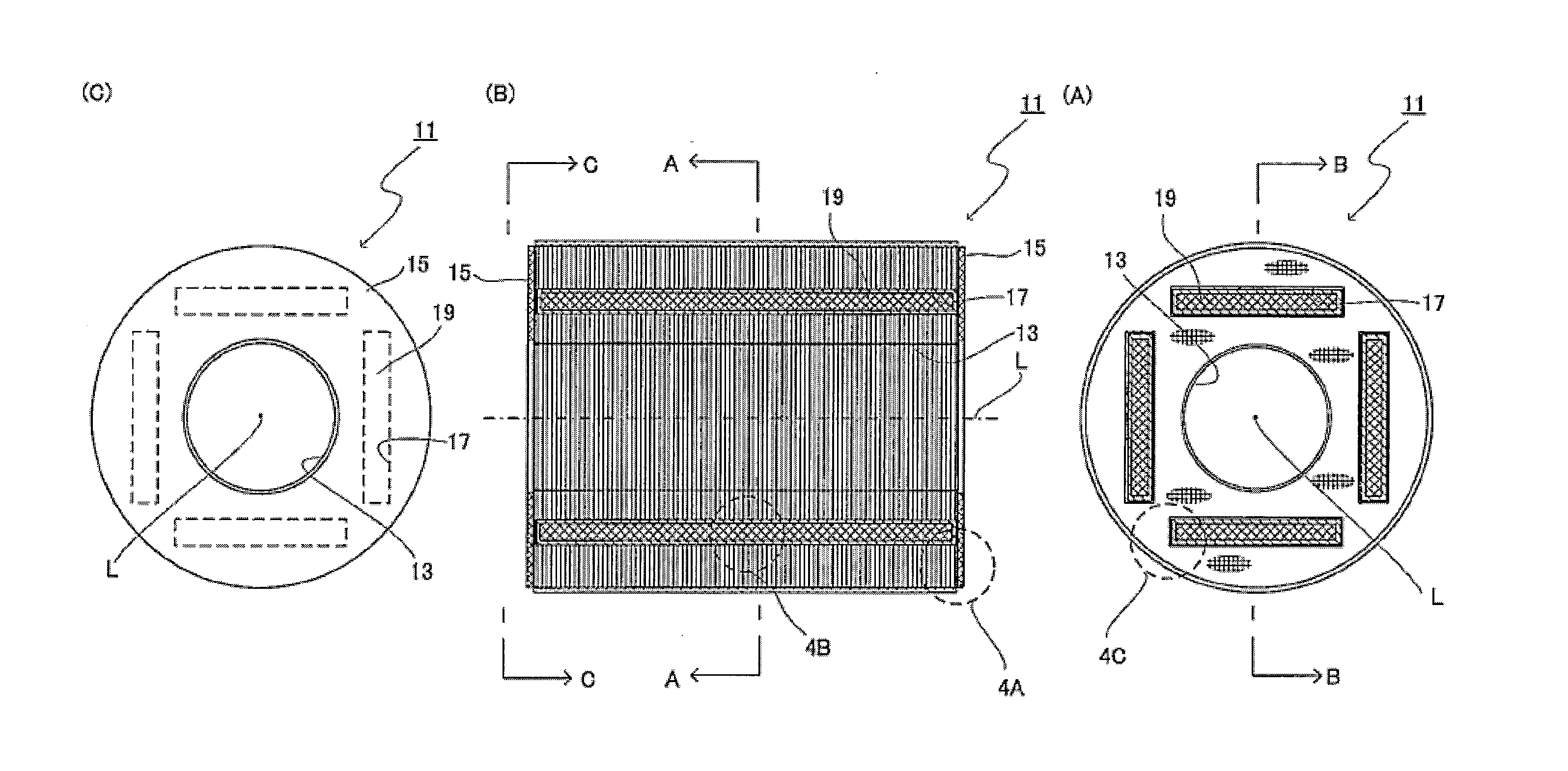
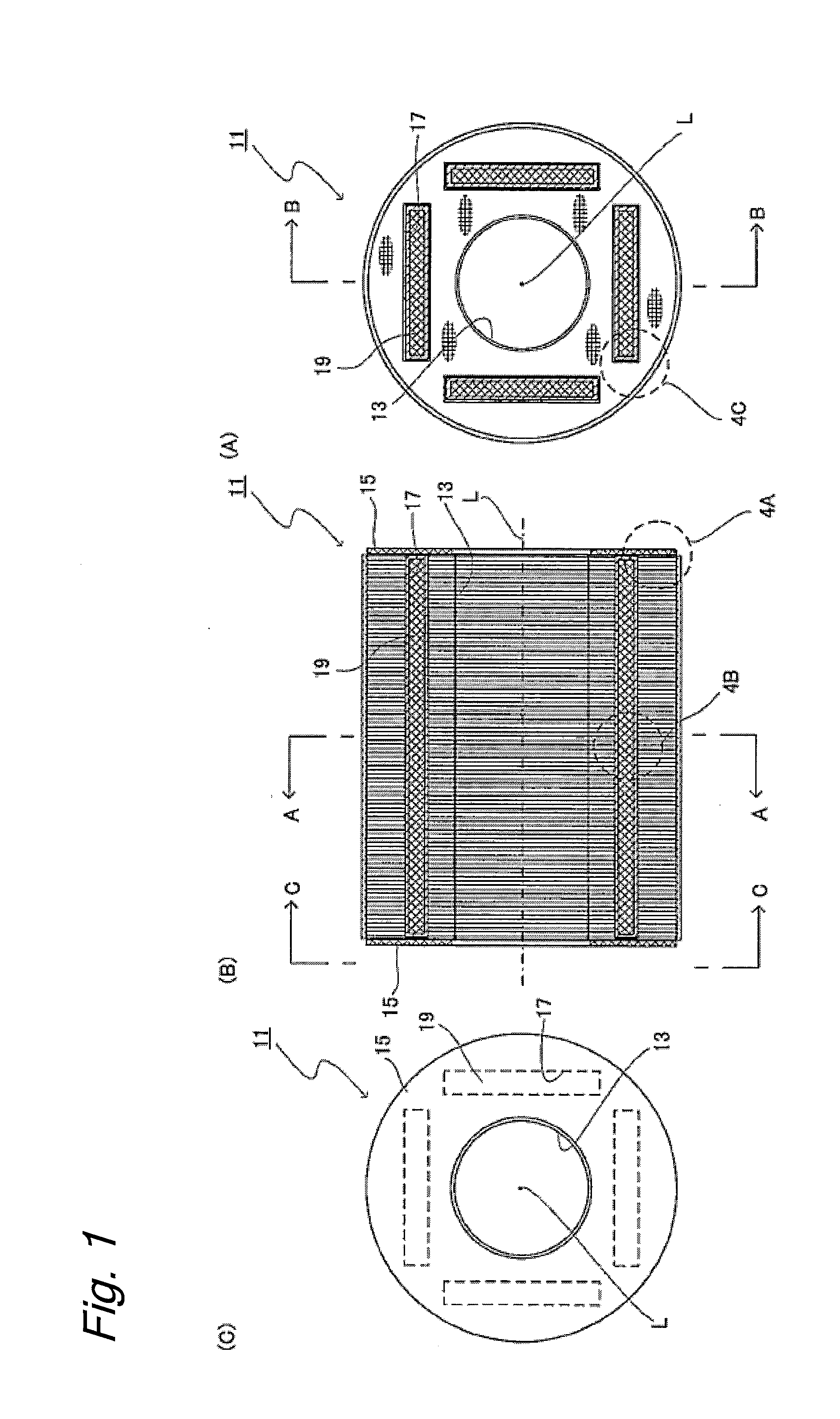
[0037]FIG. 1 shows a motor rotor 11 according to an embodiment of the invention. Here, FIG. 1A is a cross-sectional view of the motor rotor taken along the line A-A in FIG. 1B, FIG. 1B is a cross-sectional view of the motor rotor taken along the line B-B in FIG. 1A, and FIG. 1C is a left side view of the motor rotor as seen in the direction of the line C-C in FIG. 1B. The motor rotor 11 has a cylindrical shape as a whole, and a through bore portion 13 having a circular cross section is formed in an interior of the motor rotor 11. A pump rotor rotating shaft, which will be described later, is inserted into this through bore portion 13. Annular end plates 15 are attached to axial end portions of the motor rotor 11. The end plates 15 have almost the same shape as a cross-sectional shape of the motor rotor 11.

[0038]In addition, through holes 17 having a rectangular cross section are formed along an axial direction in the motor rotor 11. The through holes 17 are formed so as to extend al...


PUM


Abstract

In order to provide a motor rotor in which a permanent magnet is prevented from corroding, wherein a motor rotor for use in a motor for driving a pump rotor rotating shaft of a vacuum pump is provided which comprises a rotor core made up of a plurality of steel plates which are laminated in an axial direction and having a through hole, a permanent magnet which is disposed in the through hole, and end plates which are attached individually to axial end portions of the rotor core, wherein an adhesive is applied to a whole surface of each of the plurality of steel plates, and the plurality of steel plates are surface joined to each other and to the end plates via the adhesive.

Description

TECHNICAL FIELD[0001]The present invention relates to a motor rotor and more particularly to a vacuum pump motor rotor, a motor including the same and a vacuum pump including the motor.BACKGROUND ART[0002]For example, in a semiconductor fabrication process, vacuum techniques are used in various steps. Raised as some of examples of such vacuum techniques are a vacuum deposition method for forming a metal film, a plasma etching process for a resist removing or etching step, an ion implantation process for an impurity diffusion step, and a low pressure CVD or plasma CVD process for a silicone oxide film or nitride film forming step. Any of these processes is performed in a vacuum (or low pressure) environment, and the role played by vacuum in the semiconductor fabrication process is very important.[0003]As a vacuum pump used in a semiconductor fabrication system, there is a multi-stage roots type positive displacement vacuum pump 101 as shown in FIG. 6. The vacuum pump shown in FIG. 6 ...

Claims


Application Information

Patent Timeline
IPC IPC(8): H02K1/27F04D13/06
CPCH02K1/276H02K1/27F04D13/0606H02K15/03H02K1/28F04C25/00F04D19/04
Inventor OJIMA, YOSHINORIINADA, TAKANORIYOSHIDA, NAOYANAKAZAWA, TOSHIHARUMATAKE, KOZO
Owner EBARA CORP
Why Eureka
Try Eureka