
Triaxial magnetic field sensor

a triaxial magnetic field and sensor technology, applied in the direction of magnetic measurement, single device manufacturing, instruments, etc., can solve the problems of excessive size, limitation of gmr triaxial sensor, difficult fabrication of single-chip three-axis sensor, etc., and achieve high sensitivity, low power consumption, and high integration

Active Publication Date: 2014-09-04
MULTIDIMENSION TECH CO LTD
View PDF14 Cites 33 Cited by
  • Summary
  • Abstract
  • Description
  • Claims
  • Application Information

AI Technical Summary

Benefits of technology

The present invention is a compact triaxial sensor that has higher sensitivity and lower power consumption. It is designed to provide high-quality and reliable data with good linearity, wide dynamic range, excellent thermal stability, and low magnetic noise.

Problems solved by technology

When deposited on the same wafer, GMR and MTJ materials used for the different sensor axes have the same magnetic moments, and after annealing have the same pinned layer direction, which makes fabrication of single-chip three-axis sensors difficult.
As such, the most common approach to manufacture a GMR triaxial sensor is to package an X-axis sensor, a Y-axis sensor, and a Z-axis sensor deposited on three different substrates; such a GMR triaxial sensor suffers limitations such as excessive size, high packaging cost, and it has a lower sensitivity and higher power consumption than a MTJ sensor.
As can be seen from the above, current AMR, Hall, and GMR triaxial sensors are disadvantageous in that they have excessive size, high packaging cost, lower sensitivity, higher power consumption, and the manufacturing methods are impractical.

Method used


Image

  • Triaxial magnetic field sensor
  • Triaxial magnetic field sensor
  • Triaxial magnetic field sensor

Examples


first embodiment

[0077]in FIG. 13, the substrate 18 is wet etched to form the beveled groove, wherein MTJ elements are placed onto opposite slopes and connected through solder bumps to the ASIC component. The relative placement of the MTJ chips can cancel X and Y-axis cross-axis sensitivity and increase sensitivity to fields in the Z-axis direction. To enhance its sensitivity for the Z-axis direction the MTJ sensors can be a full bridges using various implementations including those shown in FIG. 8 and FIG. 10.

second embodiment

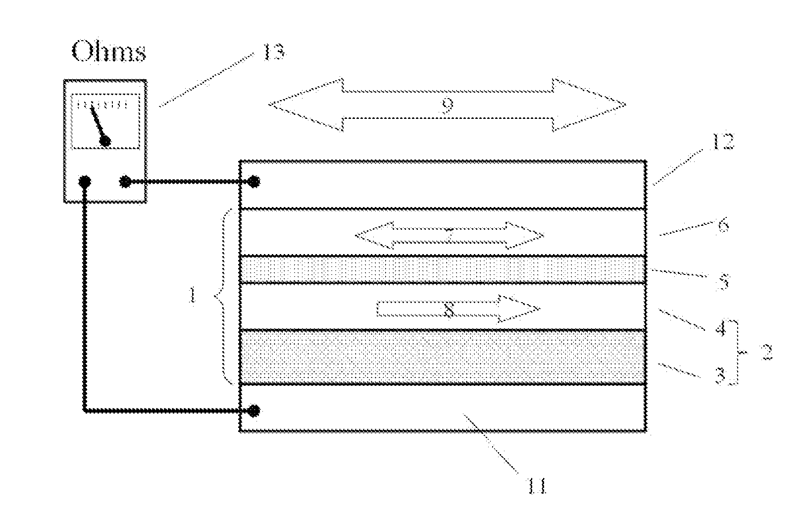
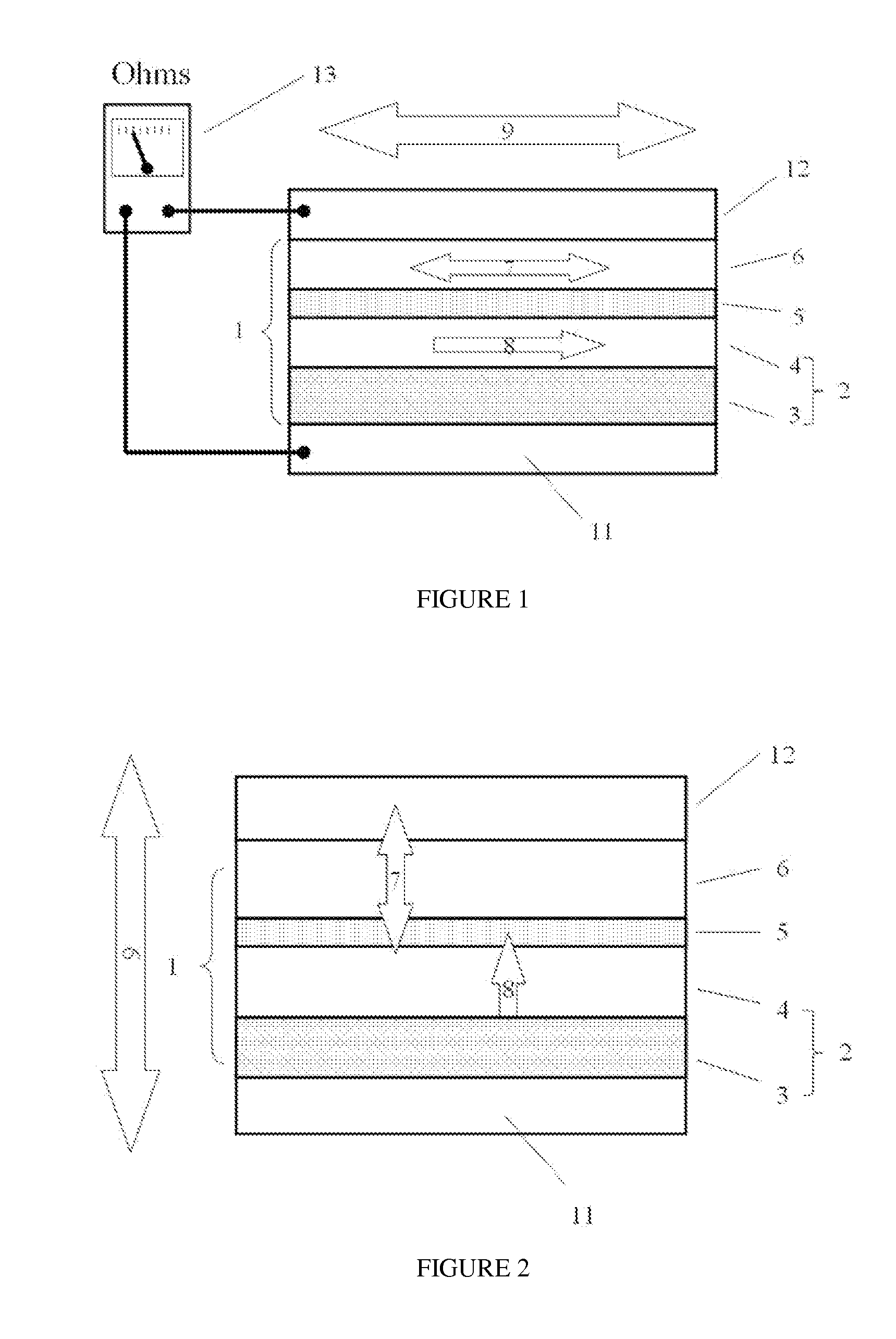
[0078]In FIG. 13, the substrate 18 prepared by wet etching to form the beveled grooves, and then MTJ bridge sensors are placed onto the opposite slopes of the groove and connected to the ASIC 19 through the solder bump, the corresponding placement the of the MTJ bridges can cancel X, Y-axis cross-axis sensitivity and increase sensitivity to fields in the Z-axis direction. The two MTJ the bridge magnetic field sensors can be push-pull full bridge sensor (FIG. 8) or referenced full-bridge sensors (FIG. 2).

[0079](2) FIG. 14 shows a vertically mounted MTJ bridge sensor. FIG. 14 shows vertically mounted MTJ bridge sensor schematic wherein the edge of the MTJ bridge sensor 20 has solder bumps 21 that are used to set the MTJ bridge sensor 20 onto the ASIC element 19 with a the 90° angle, and the solder bump 21 provides electrical connection to the ASIC 19, the chip is now sensitive to Z-axis magnetic field.

[0080](3) As shown in FIG. 2, the magnetic field bridge sensors may comprise perpend...


PUM


Abstract

The present invention discloses a triaxial magnetoresistive sensor. It comprises a substrate integrated with a biaxial magnetic field sensor, a Z-axis sensor that has a sensing direction along Z-axis perpendicular to the two axes of the biaxial magnetic field sensor, and an ASIC. The biaxial magnetic field sensor comprises an X-axis bridge sensor and a Y-axis bridge sensor. The Z-axis sensor and the two-axis sensor are electrically interconnected with the ASIC. A single-chip implementation of the triaxial magnetic field sensor comprises a substrate, onto which a triaxial magnetic field sensor and an ASIC are stacked. The triaxial magnetic field sensor comprises an X-axis bridge sensor, a Y-axis bridge sensor, and a Z-axis bridge sensor. The above design provides a highly integrated sensor with high sensitivity, low power consumption, good linearity, wide dynamic range, excellent thermal stability, and low magnetic noise.

Description

CROSS-REFERENCE TO A RELATED APPLICATION[0001]This application is a 35 U.S.C. §371 national phase application of PCT / CN2012 / 080600, filed on Aug. 27, 2012, which claims priority to a Chinese Patent Application No. CN201110251902, filed on Aug. 30, 2011, incorporated herein by reference in its entirety.TECHNICAL FIELD[0002]The invention relates to the design of the bridge type magnetic field sensor, in particular a three-axis magnetic field sensor.BACKGROUND ART[0003]In recent years Magnetic Tunnel Junctions (MTJ) have begun finding acceptance in industrial applications as a new type of magnetoresistive sensor, using the Tunneling Magnetoresistance (TMR) Effect of magnetic multilayer materials. In this effect the magnitude and direction of a magnetic field applied to the multilayered film changes the resistance of the multilayer film. The TMR effect is larger than the AMR (Anisotropic Magnetic Resistance) effect, and it also known to have better temperature stability than the Hall Ef...

Claims


Application Information

Patent Timeline
Patent Type & Authority Applications(United States)
IPC IPC(8): G01R33/02
CPCG01R33/0206G01R33/093G01R33/098G01R33/0005G01R33/0052G01R33/028G01R33/09G01R33/096
Inventor LEI, XIAOFENGZHANG, XIAOJUNLI, WEIXUE, SONGSHENG
Owner MULTIDIMENSION TECH CO LTD
Learn More