Measuring whispering-gallery-mode resonator

Active Publication Date: 2014-09-04
INST OF PHYSICS - CHINESE ACAD OF SCI +3
View PDF9 Cites 0 Cited by
  • Summary
  • Abstract
  • Description
  • Claims
  • Application Information

AI Technical Summary

Benefits of technology

[0022]As the basis of the invention, the authors set the task of improving an measuring whispering-gallery-mode resonator (hereinafter referred to as resonator) by introducing hitherto unknown coupling unit for the resonator with transmission feeder lines, which would allow increasing the coupling coefficient of the coupling unit adapted to the selected whispering gallery mode at extremely low levels of resonant scattering and non-resonant radiation. This allows a significant increasing in the signal-to-noise ratio and achieving the p

Problems solved by technology

Measurement of the surface resistance RS of the superconductor is difficult, because the value of it is very small.
The disadvantage of this device is the practical impossibility to use the dielectric resonator with lower modes in the millimeter and sub-millimeter wavelength ranges through excessive reduction in the size of the resonator and the associated difficulty of effective coupling of the cavity with transmission lines, which further reduces the accuracy and sensitivity of the measurement method.
The disadvantage of this device is the need to use two films in one act of measurement, so the number of acts of measuring individual characteristics of films increases.
In the case of open systems (due to the availability of coupling with space), this leads to two effects: 1) the field of the resonator is scattered by the waveguide, thereby reducing the eigen Q-factor of the resonator, 2) a traveling-wave field of dielectric waveguide is scattered by the resonator into space, thus reducing the efficiency of energy transfer into the resona

Method used


Image

  • Measuring whispering-gallery-mode resonator
  • Measuring whispering-gallery-mode resonator
  • Measuring whispering-gallery-mode resonator

Examples


Example

[0035]Exemplary embodiments of the present disclosure will be described hereinafter in detail with reference to the attached drawings, wherein the like reference numerals refer to the like elements. The present disclosure may, however, be embodied in many different forms and should not be construed as being limited to the embodiment set forth herein; rather, these embodiments are provided so that the present disclosure will be thorough and complete, and will fully convey the concept of the disclosure to those skilled in the art.

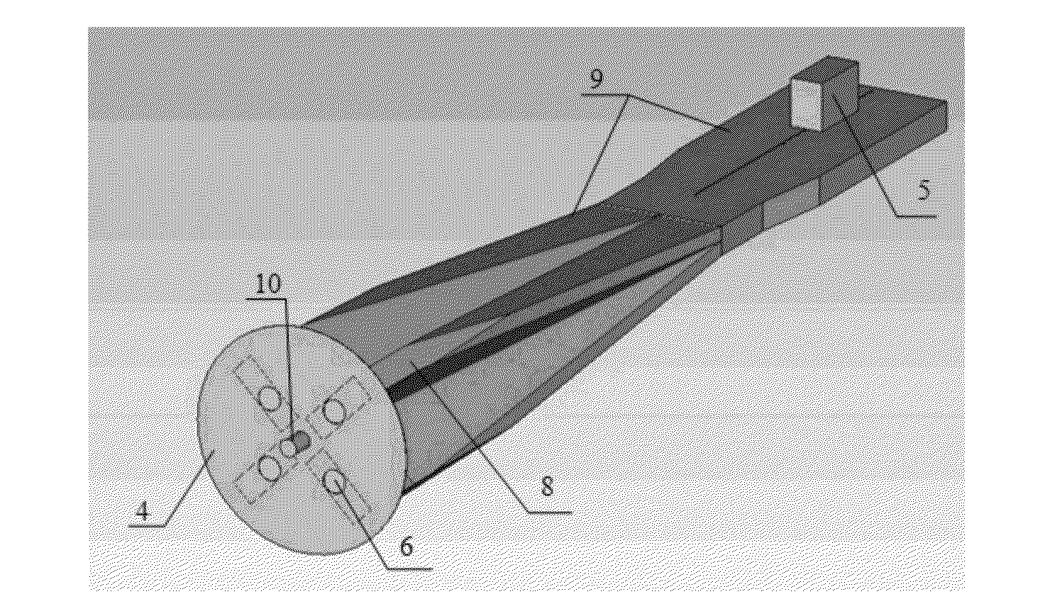
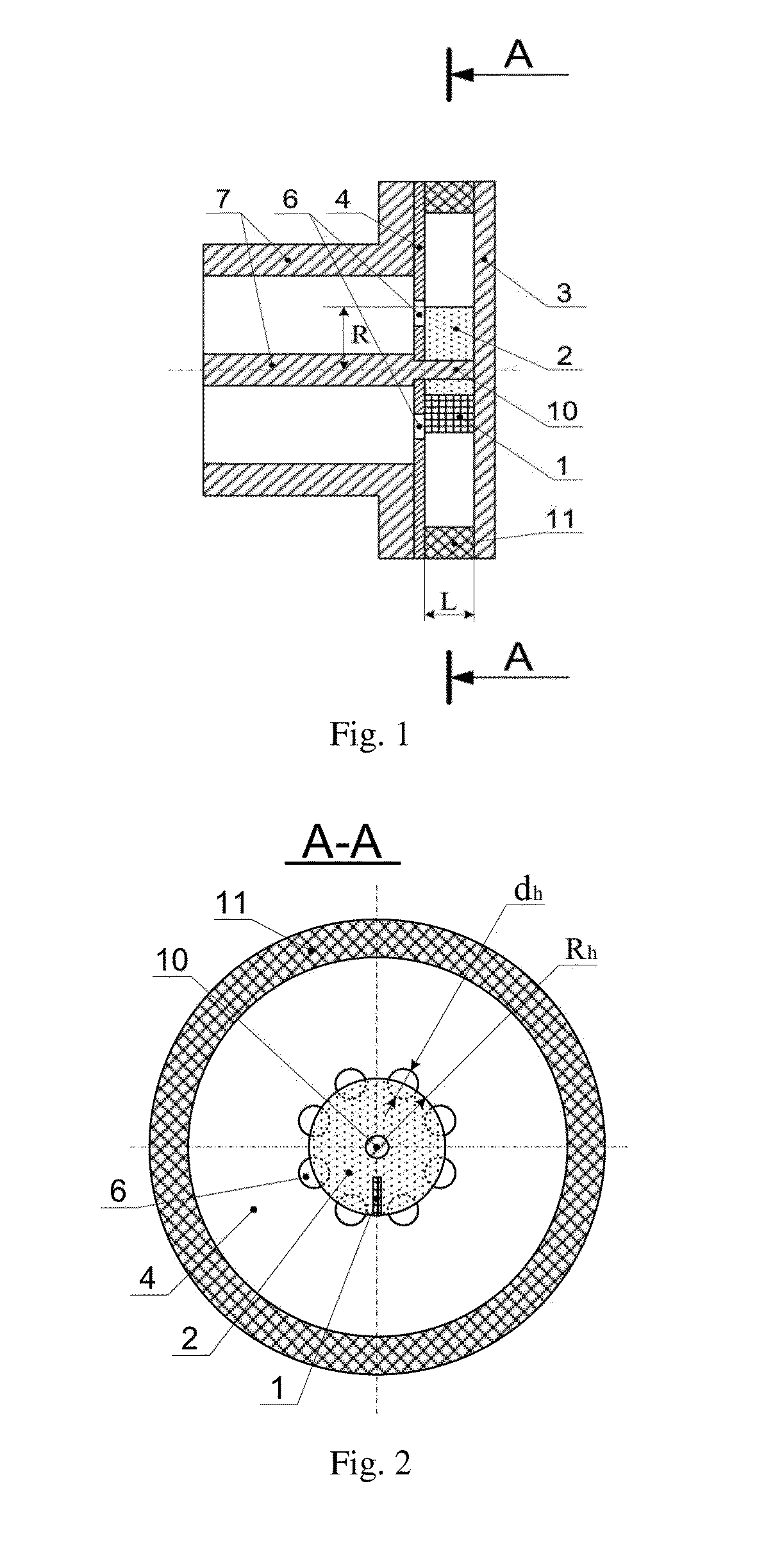
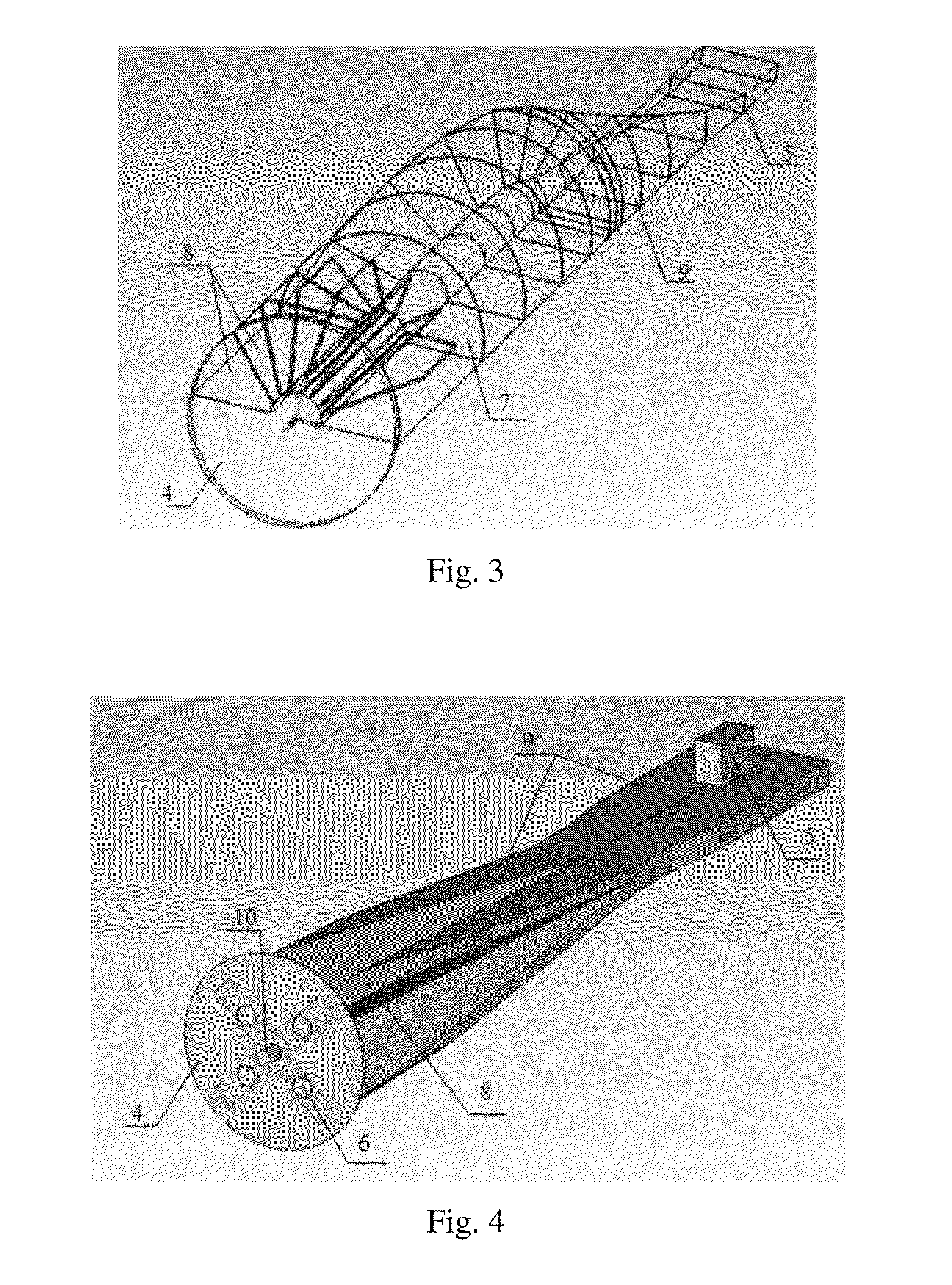
[0036]According to an exemplary embodiment of the present invention, a measuring whispering-gallery-mode resonator (hereinafter referred to as resonator), which contains the sample 1 under study, comprises a dielectric resonating body 2 with one or two flat bases perpendicular to an axis of rotation thereof, for example, the endplates 3 and 4 of material with high electrical conductivity are installed to the resonating body 2. In some cases of using the reson...


PUM


Abstract

A measuring whispering-gallery-mode resonator, comprising: a dielectric resonating body with a rotation axis; a superconducting sample under test, which is mounted to the resonating body; a coupling unit for coupling a measuring waveguide with the resonating body, wherein one side of the resonating body connected with the coupling unit is provided with a first endplate, wherein m coupling holes penetrate through the first endplate, and centers of the m coupling holes are arranged to be evenly spaced along a circle whose center is on the rotation axis; the coupling unit has a feeder line which is a coaxial waveguide, wherein an axis of the coaxial waveguide coincides with the rotation axis, and one end surface of the coaxial waveguide, which is perpendicular to the rotation axis, abuts to the first endplate; and the axial index of operated whispering gallery mode in the resonator is an integer multiple of the number m of the coupling holes.

Description

CROSS-REFERENCE TO RELATED APPLICATION[0001]This application claims the benefit of Ukraine Patent Application No. a 2013 02666 filed on Mar. 4, 2013 in the Patent Office of Ukraine, the whole disclosure of which is incorporated herein by reference.BACKGROUND OF THE INVENTION[0002]1. Field of the Invention[0003]The present invention belongs to the field of microwave technique, in particular to the measurement technique for determination of superconductor surface impedance in millimeter and sub-millimeter wavelength ranges.[0004]2. Description of the Related Art[0005]Accuracy and sensitivity of substance microwave properties measurement depend on quality (Q)-factor of the resonator. Important peculiarity of the resonator is possibility to measure samples in the forms of small ones or thin films without their pretreatment. In case of studying high temperature superconductors (HTS), measurements of HTS film microwave properties depend on amplitude of the microwave field, i.e. measuremen...

Claims


Application Information

Patent Timeline
IPC IPC(8): G01N27/04G01N22/00
CPCG01N22/00G01N27/04G01F23/284G01R27/04G01S13/88
Inventor SUN, LIANGWANG, XUWANG, JIAWU, YUNHE, YUSHENGLI, HONGHUANG, JIANGMINGLUO, SHENGCHERPARK, MYKOLASKRESANOV, VALERIIBARANNYK, OLEKSANDR
Owner INST OF PHYSICS - CHINESE ACAD OF SCI
Why Eureka
Try Eureka