Electro-optical modulator based on carrier depletion or carrier accumulation in semiconductors with advanced electrode configuration

a technology of advanced electrode configuration and electro-optical modulator, which is applied in the field of electro-optical modulators, can solve the problems of reducing signal losses in transmission lines of electro-optical modulators, and cross-talk between neighbouring signal lines of conventional electro-optical modulators of that type, so as to reduce transmission line losses, reduce cross-talk, and reduce the density of on-chip devices.

Active Publication Date: 2014-09-04
RWTH AACHEN UNIV
View PDF0 Cites 49 Cited by
  • Summary
  • Abstract
  • Description
  • Claims
  • Application Information

AI Technical Summary

Benefits of technology

[0005]There may therefore be a need for an electro-optical modulator having at least one of reduced cross-talk between the signal lines, a compact geometry and thus a high on-chip device density when more than one modulator is implemented, reduced transmission line losses resulting from efficient shielding and low cost device fabrication.

Problems solved by technology

However, conventional electro-optical modulators of that type may suffer from cross-talk between neighbouring signal lines in the push-pull configuration.
Furthermore, in order to e.g. limit such cross-talk, such electro-optical modulators may need significant space so as to provide sufficient distance between the signal lines, thereby reducing a possible on-chip device density when a plurality of modulators is to be integrated within a single chip.
Additionally, insufficient electro-magnetic shielding provisions may result in signal losses in transmission lines of the electro-optical modulator.
And, last but not least, complex electro-magnetic shielding provisions and high data transmission requirements may result in high fabrication costs.

Method used


Image

  • Electro-optical modulator based on carrier depletion or carrier accumulation in semiconductors with advanced electrode configuration
  • Electro-optical modulator based on carrier depletion or carrier accumulation in semiconductors with advanced electrode configuration
  • Electro-optical modulator based on carrier depletion or carrier accumulation in semiconductors with advanced electrode configuration

Examples


Embodiment Construction

Introduction

[0019]Electro-optical modulators are one of the key components of photonic data transmission systems such as active optical cable transmitters, datacom transmitters or complex quadrature phase shift type transmitters in Metro-Access and Long-Haul telecom networks.

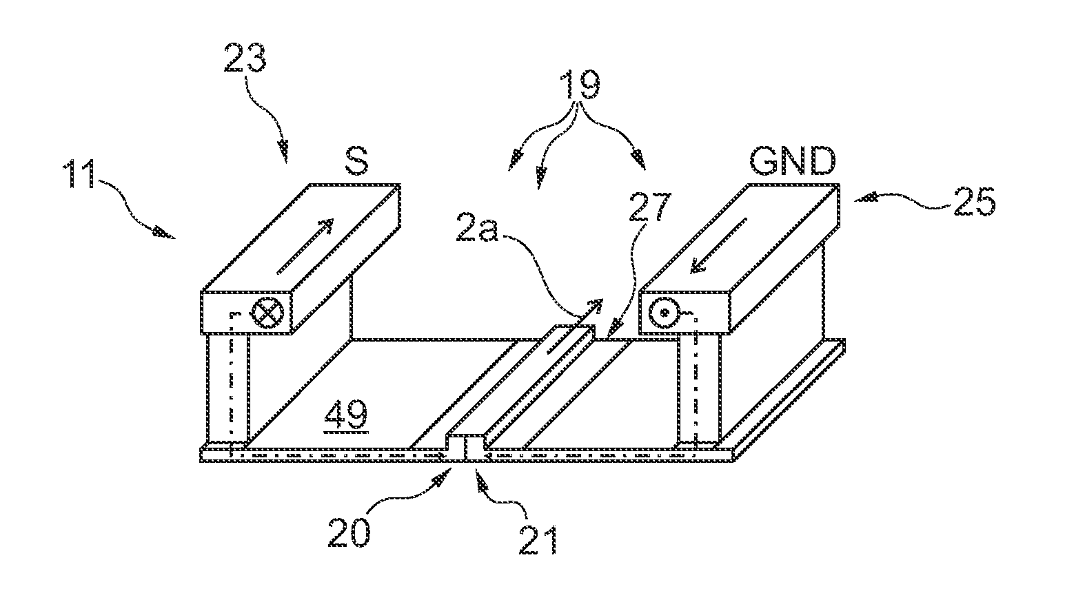
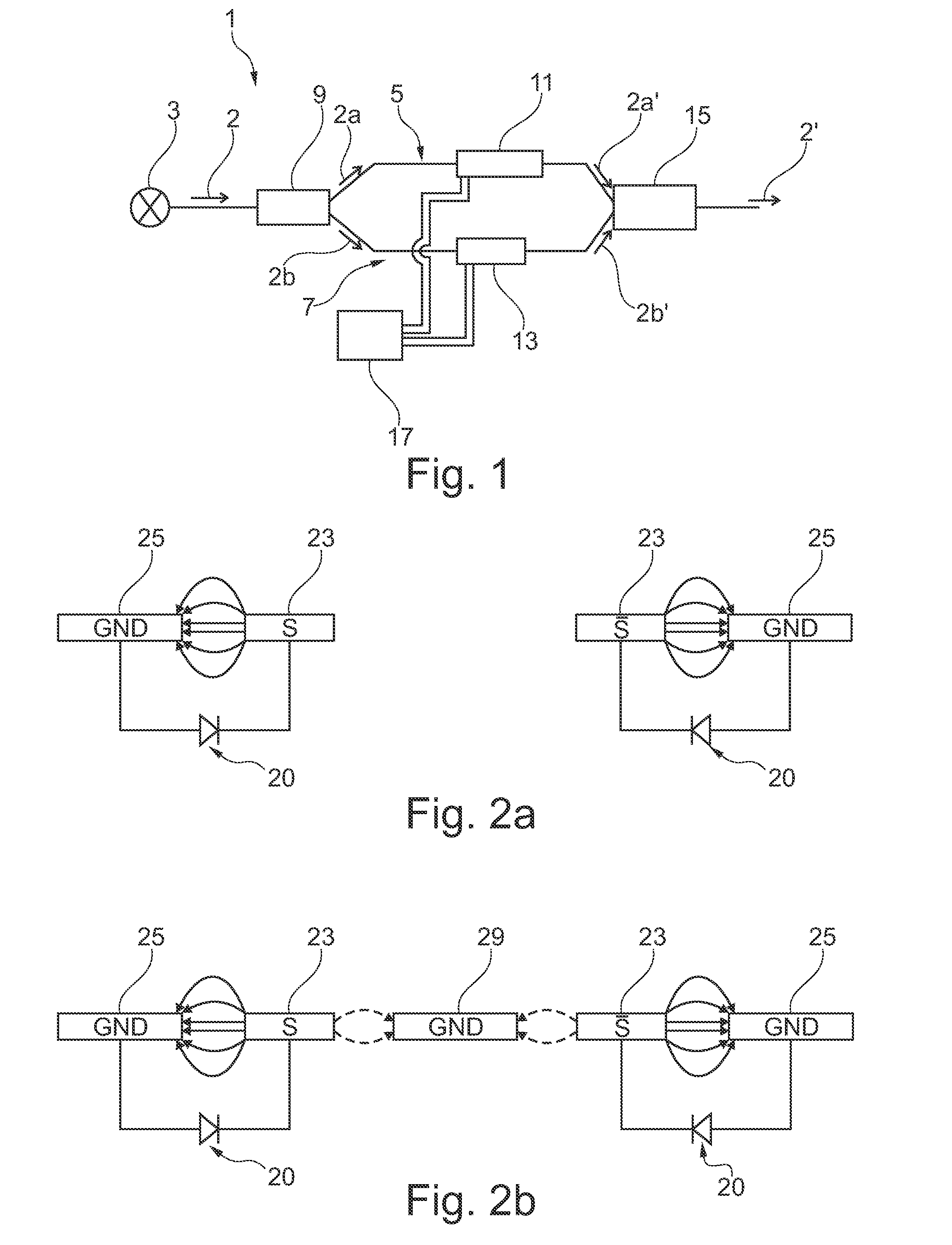
[0020]Embodiments of the invention are generally built on a state-of-the-art depletion type or accumulation type plasma electro-optical modulator 1 based on a Mach-Zehnder interferometer (MZI) architecture in push-pull configuration as schematically depicted in FIG. 1.

[0021]The MZI may be implemented as a waveguide based device that splits incoming light 2 coming from a light source 3 into two modulator-arms 5, 7 using a light splitting device 9 such as a Y-junction splitter (YS), a directional coupler splitter (DCS) or a multimode-interferometer (MMI). In both of the modulator-arms 5, 7 an electrically driven phase modulator 11, 13 is implemented that is adapted to tune the phase velocity of the propagating lig...


PUM

PropertyMeasurementUnit
frequenciesaaaaaaaaaa
frequencyaaaaaaaaaa
RF frequenciesaaaaaaaaaa

Abstract

An electro-optical modulator with two electrodes as part of a transmission line of a first phase modulator and two electrodes as part of a transmission line of a second phase modulator included in two arms of a Mach-Zehnder-interferometer. An electrical controller applies a first electrical high-frequency-modulated voltage signals between the first and second electrodes and applies a second electrical high-frequency-modulated signals between the fourth and third electrodes. The electrical controller applies signals such that voltages applied to the first and fourth electrodes have substantially a same high-frequency content, and voltages applied to the second and third electrodes have substantially the same high-frequency content. In such configuration, a constant voltage offset is produced by either the voltages applied to the first and fourth electrodes or, the second and third electrodes. Thereby, cross-talk between electrodes, electrical losses, device size and fabrication costs may be reduced.

Description

FIELD OF THE INVENTION[0001]The present invention relates to an electro-optical modulator based on carrier depletion or carrier accumulation in pn-diodes or in semiconductor-insulator-semiconductor capacitors.BACKGROUND OF THE INVENTION[0002]An electro-optical modulator may be used for converting electrical signals into optical signals. Therein, analogue or digital electrical signals may be input to the electro-optical modulator and the electro-optical modulator may then output corresponding optical signals. The optical signals in a form of amplitude or phase modulated light may then e.g. be transmitted through optical fibres. In order to enable data transmission at e.g. more than one gigabit per second (Gbps), the electro-optical modulator should be able to convert signals in a radiofrequency (RF) range.[0003]Various types of electro-optical modulators have been proposed. High data transmission rates have been realized with a depletion type plasma modulator with pn-diodes as well a...

Claims


Application Information

Patent Timeline
Patent Type & Authority Applications(United States)
IPC IPC(8): G02F1/025
CPCG02F1/025G02F1/0121G02F1/2257H04B10/505G02F1/2255G02F1/0152
Inventor WITZENS, JEREMYMERGET, FLORIAN
Owner RWTH AACHEN UNIV
Why Eureka
Try Eureka