
Low Profile Wheel Chocking System and Chock Construction

a low-profile, chock-type technology, applied in the direction of braking systems, transportation and packaging, transportation items, etc., can solve the problems of brittleness of the copolymer chock body, rapid performance problems of the chock body, and material brittleness, so as to reduce the unit's weight, reduce the impact on the chock structure, and increase the moment of inertia and thus the effect of bending resistan

Active Publication Date: 2014-09-04
HOLLAND CO
View PDF2 Cites 7 Cited by
  • Summary
  • Abstract
  • Description
  • Claims
  • Application Information

AI Technical Summary

Benefits of technology

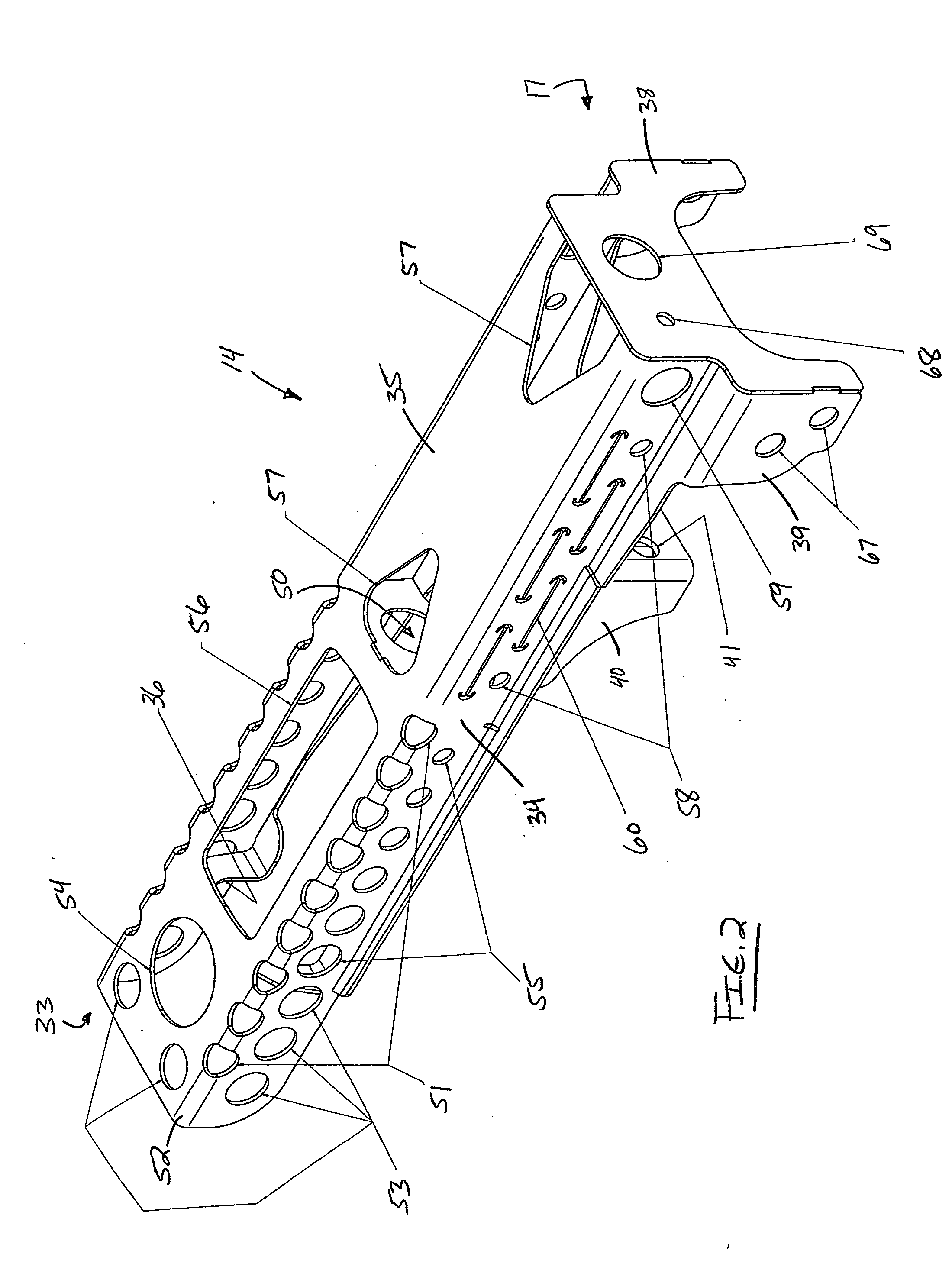
The patent is about a new design of a chock body that meets customer requirements. The design is made of a sheet metal formed C-channel construction with additional strips of metal at the tips that define the channel mouth. The main advantages of this design are the production of two interconnected I-beams that carry, distribute, and cushion the stresses and strains when the device is in use. Additionally, the design has many apertures for different purposes, such as reducing the weight of the unit, allowing elastic response to the loads, and controlling elastic response in the primary body construction. The strain relief slots tend to open vertically providing a sink for strain energy in the form of elastic bending and buckling in the slot region, which increases the bending resistance against the applied load. This design also allows for easier installation and reduces the impact on the chock structure itself as well as on the automobile being secured.

Problems solved by technology

This chock quickly had performance problems in the field, often releasing itself from the railcar deck and allowing damage to the cargo.
Environmental extremes are well known to cause problems for the copolymer chock body's plastic material exemplified by Moyer and Bullock.
Cold temperatures render the material brittle and subject to fracture during unloading operations, when conditions also require the breaking of ice that has adhered to the device during transport.
Hot weather renders the material more flexible and soft, increasing the likelihood that the device may fail under loading during impact conditions such as those described above.

Method used


Image

  • Low Profile Wheel Chocking System and Chock Construction
  • Low Profile Wheel Chocking System and Chock Construction
  • Low Profile Wheel Chocking System and Chock Construction

Examples


Embodiment Construction

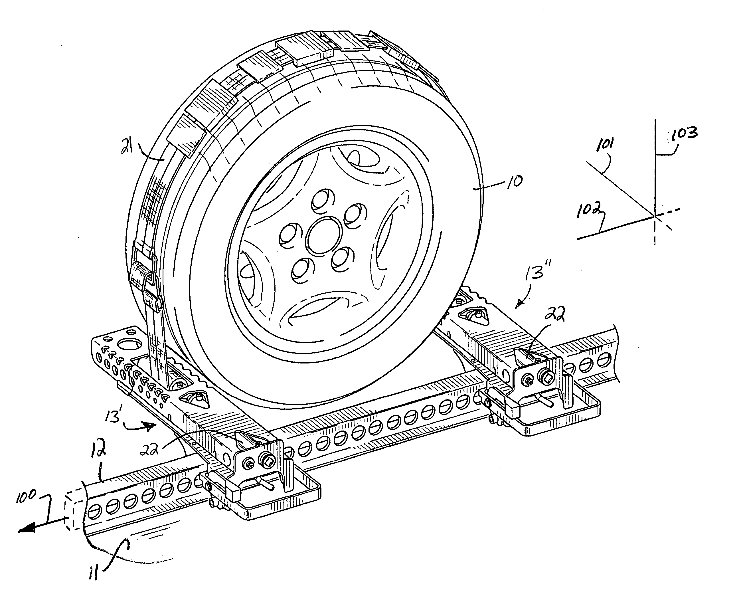
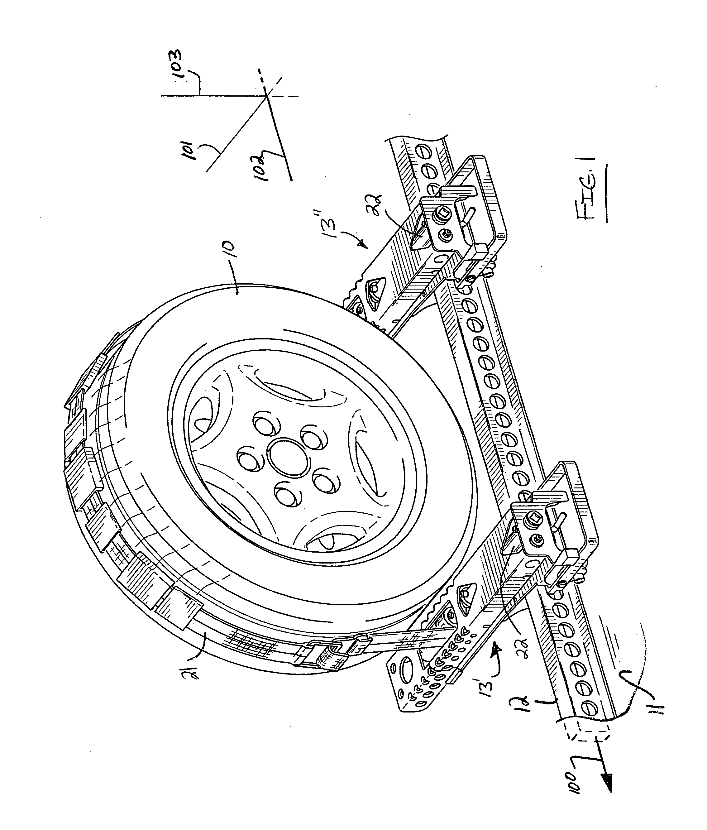
[0052]The present invention essentially provides a low-profile, primarily metallic, vehicular wheel chock construction and chocking system for chocking and restraining a vehicular wheel 10 borne upon a support surface 11 adjacent a rail 12. The reader will note that the each chock assembly as depicted and referenced at 13′ and 13″ of the chocking system according to the present invention has a primary length extending in a first dimension, which dimension is generally indicated at 101 in FIG. 1.

[0053]A diagrammatic right-handed Cartesian system generically depicts the first (or X) dimension at 101, a second (or Y) dimension at 102, and a third (or Z) dimension at 103 throughout the drawing representations. An attempt has been made to repeatedly and dimensionally define the invention to aid the reader's comprehension thereof. In FIG. 1, a three-dimensional representation appears, and two-dimensional representations appear in subsequent drawing figures.

[0054]As may be understood from ...


PUM


Abstract

A wheel chock is constructed from metallic material has an elongate primary body construction. The primary body construction has a Π-shaped transverse cross-section formed by an upper C-shaped channel construction and a lower planar basal construction. The basal construction has U-shape that extends orthogonally relative to the C-shape of the channel construction. The Π-shaped transverse cross-section bears and distributes stress imposed on the primary body construction. The C-shaped channel construction preferably includes a series of apertures for reducing weight and controlling elastic response of the primary body construction. Among these apertures are edge-based apertures, arm-based stress relief slots, and aligned apertures having sequentially decreasing diameters.

Description

BACKGROUND OF THE INVENTION[0001]1. Field of the Invention[0002]The present invention generally concerns a wheel chocking system for securing motor vehicles on the decks of transporters as exemplified by railway cars. More particularly, the present invention concerns a low-profile, high strength, metallic chock construction for restraining and securing a vehicular wheel to a wheel support surface.[0003]2. Discussion of the Prior Art[0004]For many years, vehicular wheel-to-railcar securement means were defined by tie down chains which interconnected the vehicle body and the structure of the railcar and which were tightened to compress the suspension springs of the vehicle. More recently, increasing attention has been given to restraint schemes employing vehicular wheel chocks.[0005]Early vehicular wheel chock constructions and chocking systems employed cast chock constructions consisting of lightweight polymeric or aluminum type materials as exemplified by those mechanisms disclosed ...

Claims


Application Information

Patent Timeline
Patent Type & Authority Applications(United States)
IPC IPC(8): B60P3/077
CPCB60P3/077B60P3/075B61D45/004
Inventor MORIN, ANDREW J.
Owner HOLLAND CO
Learn More