Segmented Fiber Nuclear Level Gauge

a level gauge and segmented fiber technology, applied in the direction of liquid/fluent solid measurement, material analysis using wave/particle radiation, instruments, etc., can solve the problems of high complexity and cost, rigid crystals, and difficult custom manufacturing,

Active Publication Date: 2014-09-18
VEGA AMERICAS
View PDF7 Cites 15 Cited by
  • Summary
  • Abstract
  • Description
  • Claims
  • Application Information

AI Technical Summary

Benefits of technology

[0013]The needs are met according to the invention, which provides a new and improved nuclear gauge which is not limited by the attenuation length of the scintillator and yet does not suffer from undue complexity or excessive cost.

Problems solved by technology

Scintillating fibers can be readily curved to match the curvature of a particular bin, whereas crystals are rigid and difficult to custom manufacture.
Crystals are practically limited to approximately 10 foot lengths because of the difficulty of manufacturing bars in longer sizes.
Unfortunately, the solutions illustrated in FIGS. 4 and 5 suffer from high complexity and cost, due to the replication of the PMT 12 and electronics 10 and the requirement for a summation electronics unit 20, rendering this form of gauge uncompetitive with a single fiber bundle in many environments; however, as noted, a fiber bundle suffers from attenuation losses at long lengths.

Method used


Image

  • Segmented Fiber Nuclear Level Gauge
  • Segmented Fiber Nuclear Level Gauge
  • Segmented Fiber Nuclear Level Gauge

Examples


Embodiment Construction

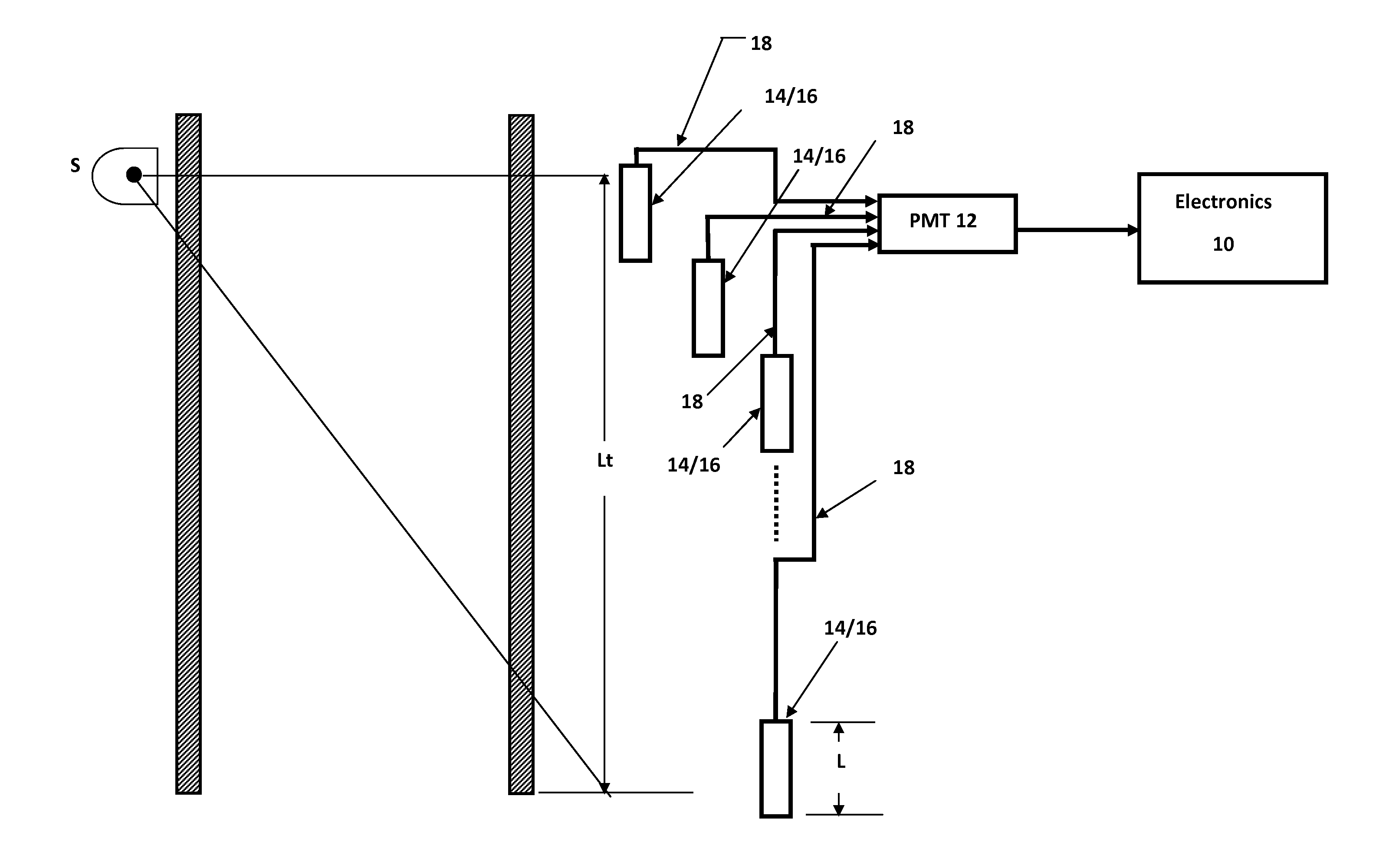
[0023]FIG. 6 shows a level sensing gauge in accordance with the present invention. In this gauge, plural scintillators 14 / 16 are arranged in a serial fashion to detect radiation passing through the bin. These scintillators may be crystals or fiber bundles (e.g., bundles of greater than 300 fibers in a 1 inch diameter bundle), or may be a mixture of crystals and fiber bundles, as suits a particular application. Importantly, the scintillators can be sized so that none is longer than the attenuation length of the scintillator medium.

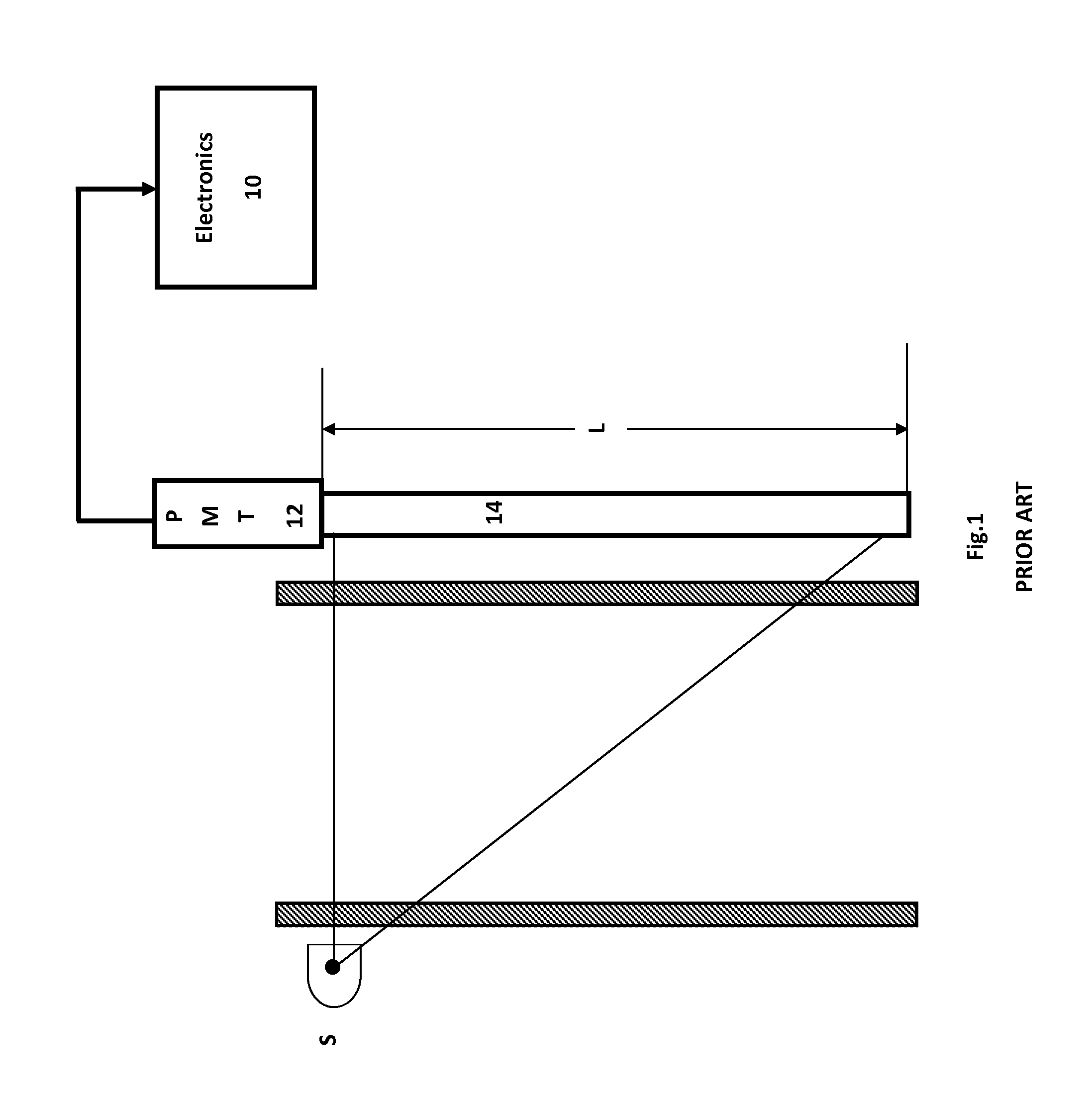
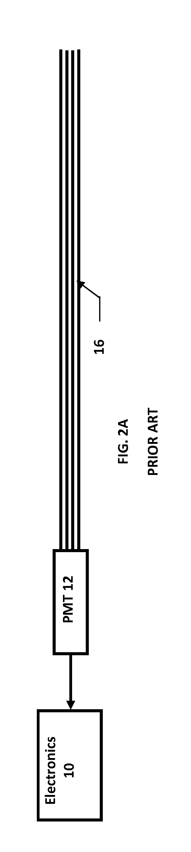
[0024]In contrast to the prior art systems shown in FIGS. 5 and 6, the invention greatly simplifies the detection of light from the scintillators by coupling the light from each scintillator via a light guide 18 to a common photomultiplier tube 12. The light guide may be of glass or acrylic / PMMA, for example, optimized for the light wavelength that is generated by the scintillators.

[0025]Thus, the invention uses multiple scintillators but simplifies the ele...


PUM

PropertyMeasurementUnit
lengthaaaaaaaaaa
diameteraaaaaaaaaa
attenuation lengthaaaaaaaaaa

Abstract

A nuclear level sensing gauge for measuring the level of product in a bin utilizes a plurality of scintillators arranged in a serial fashion. A source of nuclear radiation is positioned adjacent the bin, and the scintillators, which may be bundles of one or more scintillating fibers or scintillating crystals, are positioned in a serial fashion adjacent the bin opposite the source of nuclear radiation, such that nuclear radiation passing through the bin impinges upon the bundles. Light guides carry photons emitted by the scintillators—which are indicative of radiation passing through the bin—to a common photomultiplier tube. The tube is connected to electronics which convert counts of photons from the PMT into a measure of the level of radiation-absorbing product in the bin.

Description

BACKGROUND OF THE INVENTION[0001]In many industrial environments, it is necessary to detect the level of product in a holding tank or bin. Level sensors are typically attached to the holding tank or bin, and electrically connected to remote gauges at a control room or other central location, where technicians or control systems may monitor the status of the bins to provide the appropriate process control.[0002]Various technologies have been developed for level sensing. These include various contact sensing technologies using floats or drop weights, as well as various non-contact technologies such as reflecting electromagnetic radiation or ultrasonic vibrations from the surface of the product in the bin to determine the height of the product.[0003]In some applications, it is particularly important to move the sensor away from the product. For example, in a foundry where the level of a hot melt of steel or ore is to be level sensed, it is particularly important to keep the level senso...

Claims


Application Information

Patent Timeline
Patent Type & Authority Applications(United States)
IPC IPC(8): G01N23/08G01T1/20G01T1/202
CPCG01N23/08G01T1/202G01T1/2006G01T1/201G01F23/288G01F23/2885
Inventor CAHILL, BONAVENTURENIINEMETS, THOMAS
Owner VEGA AMERICAS
Why Eureka
Try Eureka