Electronically steerable planar phase array antenna

a phase array antenna and electric steering technology, applied in the manufacture of antenna arrays, antenna equipment with additional functions, antennas, etc., can solve the problems of large mobile terminals, high maintenance costs, and relatively slow beam steering speed, so as to improve response time and reduce the effect of bulky mobile terminals and low profil

Inactive Publication Date: 2014-09-18
ALCAN SYST GMBH
View PDF5 Cites 101 Cited by
  • Summary
  • Abstract
  • Description
  • Claims
  • Application Information

AI Technical Summary

Benefits of technology

[0012]Low-cost, lightweight, electronically steerable phased arrays which can be fabricated by using automated manufacturing techniques are of interest for mobile terminals such as for automobiles, airplanes and radars. The antennas main beam direction can be continuously steerable in order to provide the services, e.g. wireless internet or broadcasting, simultaneously on moving vehicles via satellite. Planarity and aesthetic appearance of the antenna with low-profile has to be maintained since these are other critical issues, i.e., for automobile industry. Such an antenna requires compact, low loss, electronically tunable phase shifters which can be integrated to the radiating elements and feeding network. A biasing network is necessary by which all phase shifters can be biased individually. Such an electronically steerable antenna is subject of the invention.SUMMARY OF THE INVENTION
[0013]This invention provides a low profile, electronically steerable, planar phased array antenna whose main beam can be continuously steerable in one or two dimensions. The antenna comprises an input, feed network, at least one power divider (combiner), at least one electronically tunable phase shifters, a biasing network and at least two radiating elements. The electronically steerable phased array antenna comprises a stack of at least three dielectric substrates, preferred uniform dielectric substrates, at least two of which are solid and can carry a plurality of electrodes. An individual element of the array antenna comprises at least an electronically tunable phase shifter, a biasing network and a radiating element. The phase shifter electrodes are grouped in order to form the plurality of individual antenna elements whereas a single uniform substrate can carry electrodes for any number of antenna elements. The substrates may furthermore carry electrodes for the feed network. A continuously variable dielectric being either liquid or solid is sandwiched by two of the aforementioned solid dielectric substrates. Electronically tunable phase shifters utilizing the variable dielectric substrate are thereby integrated into the antenna. The dielectric constant of the variable dielectric substrate and therefore the electrical characteristic of the phase shifters are controlled continuously in order to achieve a desired differential phase shift between the radiating elements for a continuous beam steering, so that the antenna can be adjusted in elevation and azimuth planes.
[0014]In an embodiment the antenna comprises a plurality of power dividers and / or a plurality of electronically tunable phase shifters and / or a plurality of radiating elements. The electronically steerable phased array antenna is built as a stack of at least three dielectric materials. These materials are a front dielectric substrate (solid), a variable dielectric (solid or liquid) and back dielectric substrate (solid). One of the major advantages of the invention is that the phase shifter and all the other components are not prefabricated and assembled into a large one when an antenna is built; instead they are fabricated on large simultaneously on the three mentioned substrates.
[0015]Electronically tunable phase shifters based on planar transmission lines, preferably microstrip lines, are integrated to the antenna. The dielectric properties of the variable dielectric material, and therefore the electrical characteristics of the phase shifter can be changed by applying a bias voltage.
[0016]According to another aspect of the invention, instead of the microstrip lines, loaded lines can be used as transmission lines. Using a loaded line phase shifter, the LC layer thickness can be reduced to a few micro meters and therefore the response time is improved considerably. The planar transmission lines are also called the phase shifter electrodes or electrodes of the phase shifter.
[0017]A preferred example of an antenna constructed in accordance with the invention has 4 (2×2) radiating elements. It is a planar antenna with low profile. The antenna utilizes liquid crystal (LC) material as a variable dielectric substrate. Similar to the LC display technology, LC is sandwiched between the front and back dielectric substrates. A LC material having a maximum loss tangent of 0.05 is preferred as for example nematic LC. Other types can be used as well but performance will be poor.

Problems solved by technology

These kinds of mobile terminals are bulky, have relatively slow beam steering speed, i.e. 45° / s, sensitive to the gravitational force and require high maintenance costs since the mechanical systems are used.
These antennas are low-weight and low-profile whereas the challenge is high price of the respective terminal due to its expensive electronics.
For such a large array, i.e. with 16×16 radiating elements, compactness of the electronically tunable phase shifters become an issue.
However, compact design of an electrically tunable phase shifter which has a 360° differential phase shift, is still challenging.
However, practical problems such as biasing the tunable phase shifters individually and feeding the RF signal to the antenna have not been discussed.
However, this is not a planar device.
Such phase shifters as described in these patent documents can not be used in order to fabricate a low profile antenna.
Planarity and aesthetic appearance of the antenna with low-profile has to be maintained since these are other critical issues, i.e., for automobile industry.

Method used


Image

  • Electronically steerable planar phase array antenna
  • Electronically steerable planar phase array antenna
  • Electronically steerable planar phase array antenna

Examples


Embodiment Construction

[0062]In the following, a detailed description is given according to one possible embodiment of the present invention. The embodiment is not dedicated to present every features of the invention instead it provides a basic understanding of some aspects of the invention. It is a two-dimensional steerable antenna which can be used either in receiving or transmitting mode since it is a passive and reciprocal antenna. However, most of the description is given only for a receiving antenna in order to explain the invention in a clear way. The illustrations and relative dimensions may not necessarily be scaled in order to illustrate the invention more efficiently.

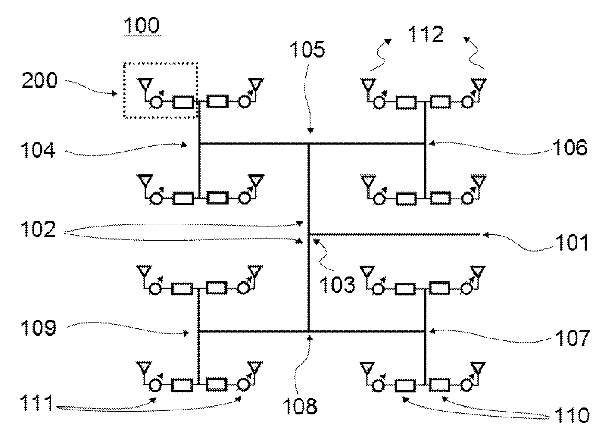
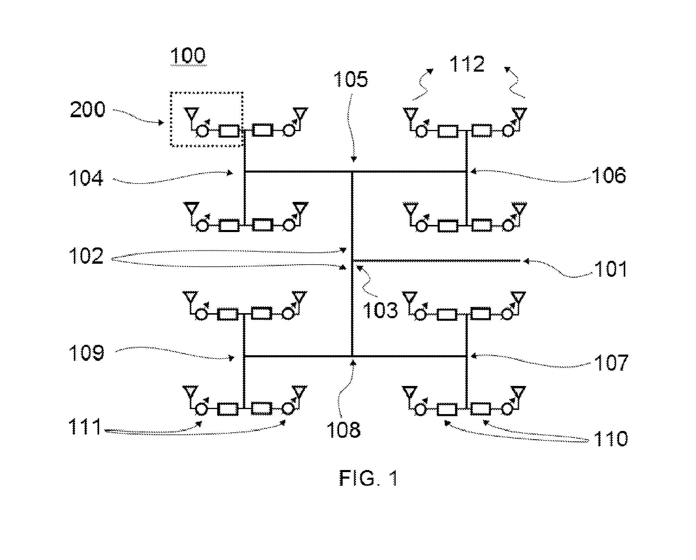
[0063]Referring to the drawings, FIG. 1 is a block diagram of an electronically steerable phased array antenna 100 according to the present invention. The phased array antenna includes signal input port 101 for example a RF signal input port, feeding network 102, plurality of power combiners 103-109, plurality of DC block structure...


PUM

PropertyMeasurementUnit
frequenciesaaaaaaaaaa
frequencyaaaaaaaaaa

Abstract

A two-dimensional (2-D) beam steerable phased array antenna is presented comprising a continuously electronically steerable material including a tunable material or a variable dielectric material, preferred a liquid crystal material. A compact antenna architecture including a patch antenna array, tunable phase shifters, a feed network and a bias network is proposed. Similar to the LC display, the proposed antenna is fabricated by using automated manufacturing techniques and therefore the fabrication costs are reduced considerably.

Description

[0001]A two-dimensional (2-D) beam steerable phased array antenna is presented comprising a continuously electronically steerable material including a tunable material or a variable dielectric material, preferred a liquid crystal material. A compact antenna architecture including a patch antenna array, tunable phase shifters, a feed network and a bias network is proposed. Similar to the LC display, the proposed antenna is fabricated by using automated manufacturing techniques and therefore the fabrication costs are reduced considerably.STATE OF THE ART[0002]This invention relates to a phased array antenna. More specifically, the invention relates to an electronically steerable phased array antenna based on voltage tunable phase shifters whose low loss dielectric material can be tuned with an applied voltage.[0003]In recent years, demand for steerable antennas increased dramatically for mobile terminals due to the rapid development of broadcast satellite services. Wireless internet, ...

Claims


Application Information

Patent Timeline
Patent Type & Authority Applications(United States)
IPC IPC(8): H01Q21/06H01Q21/00H01Q3/34
CPCH01Q21/061H01Q21/0087H01Q3/34H01Q1/38H01Q1/44H01Q3/44H01Q21/065Y10T29/49018
Inventor JAKOBY, ROLFKARABEY, ONUR HAMZAGOELDEN, FELIXMANABE, ATSUTAKA
Owner ALCAN SYST GMBH
Why Eureka
Try Eureka