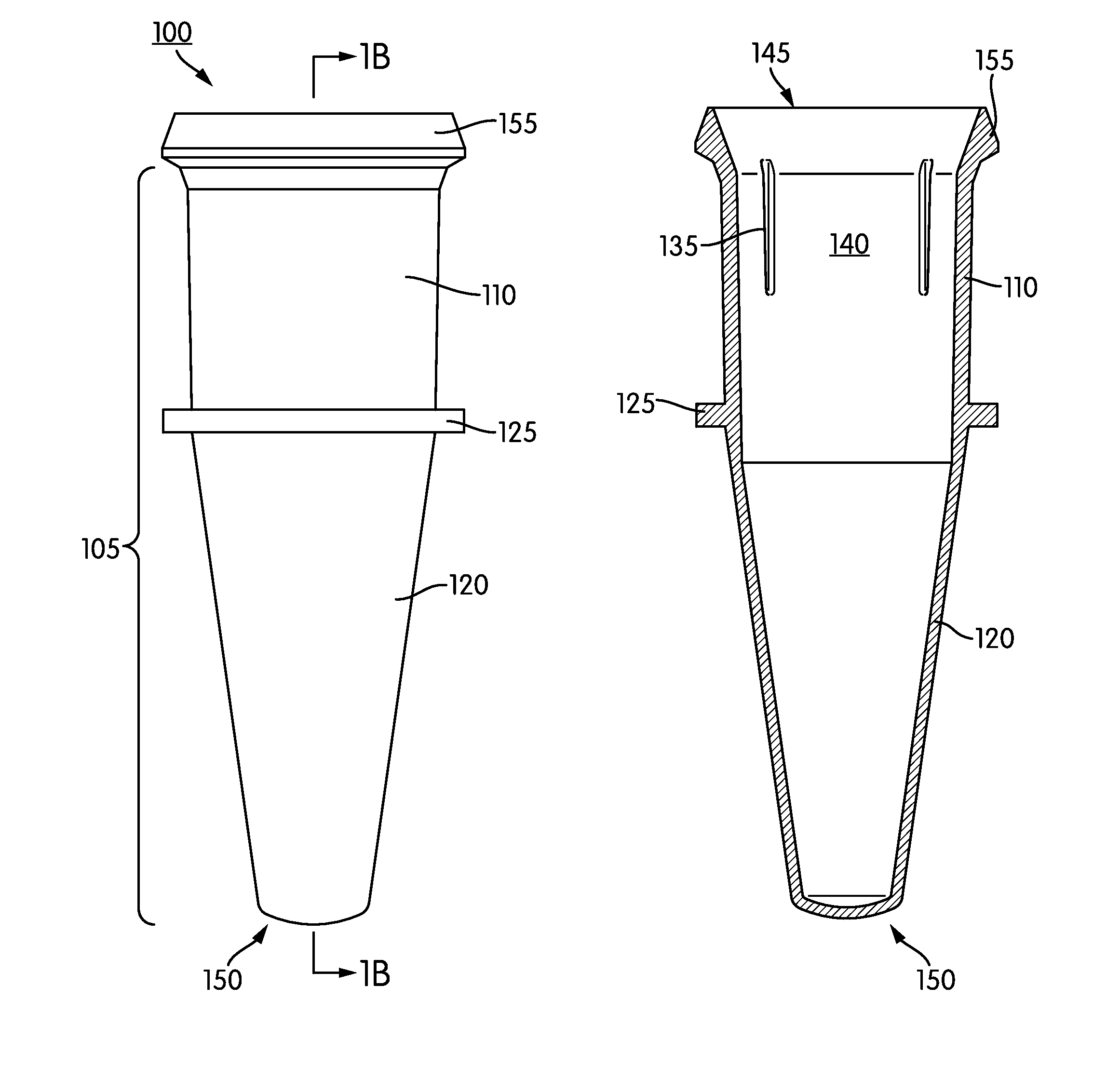
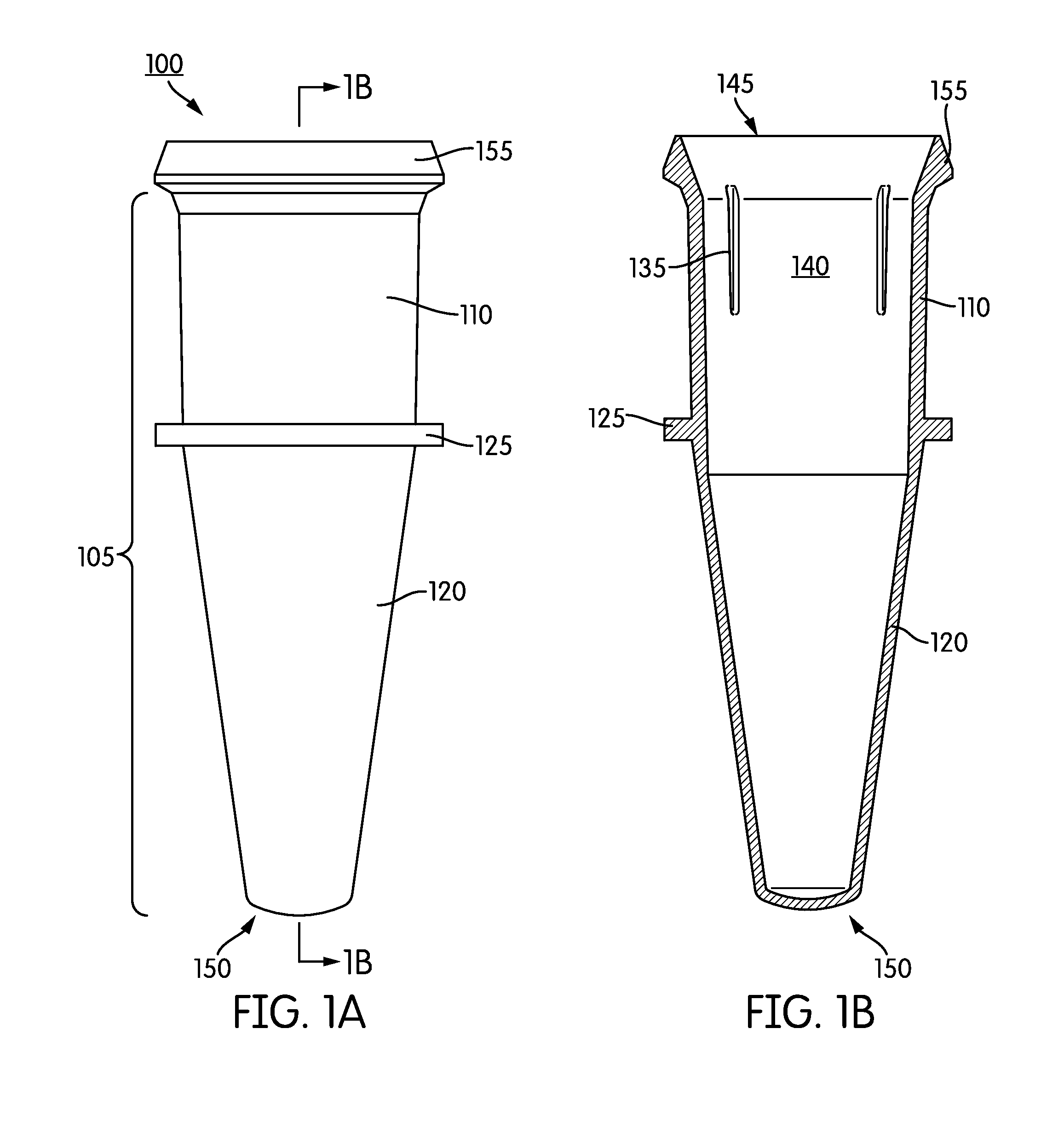
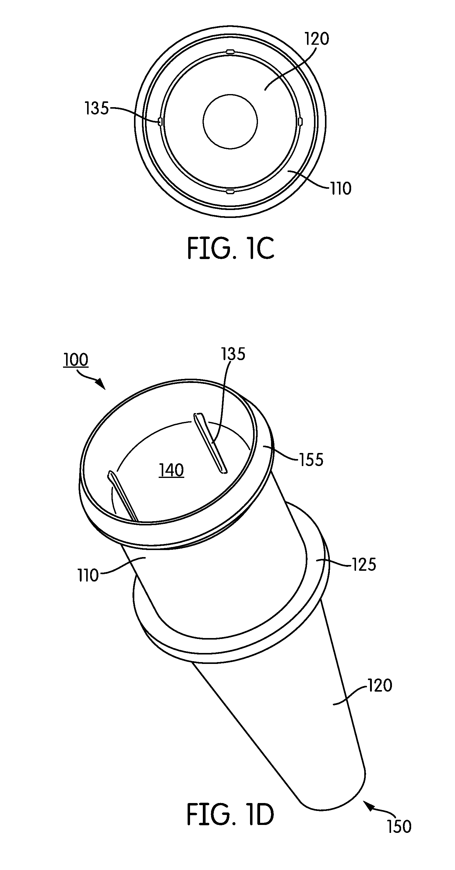
Reagent wells containing lyophilized reagents

Active Publication Date: 2014-09-18
GEN PROBE INC
View PDF4 Cites 11 Cited by
  • Summary
  • Abstract
  • Description
  • Claims
  • Application Information

AI Technical Summary

Benefits of technology

[0011]In another aspect, the disclosure provides a cap securable to the single-piece receptacle. The cap includes a lower portion having an outer surface for sealing engagement of an inner surface of the open upper end of the body, the outer surface including one or more annular ring(s), an upper portion having a length, an inner surface, an outer surface, and an open end configured for engagement with an automated pipettor, and further including one or more recess(es), which can be concave in shape, disposed on the outer surface thereof extending along at least part of the length of the upper portion, and one or more linear rib(s) disposed on the inner surface of the upper portion, each linear rib having a length corresponding to the length of at least one of the recesses, and wherein each of the one or more linear ribs is positioned on the inner surface of the cap in a manner that corresponds to at least one of the recesses such that at least one linear rib lies on an inner surface of the cap that directly opposes the position of at least one recess on the outer surface of the cap, and a lip positioned between, and extending radially away from, the upper and lower portions, the lip including a plurality of locking arms extending toward the lower portion of the cap for securely engaging the lip of the receptacle. In various embodiments, the number of linear ribs corresponds to the number of recesses in a one-to-one relationship, and the number of recesses disposed on the outer surface of the cap is selected from the group consisting of 2, 3, 4, 5, 6, 7, and 8. The lower portion of the cap may include 1, 2, or 3 annular rings for sealing engagement of the inner surface of the body of the receptacle.
[0012]In certain embodiments, the locking arms comprise a snap fit attachment for securely engaging the lip of the receptacle. The number of locking arms may be selected from the group consisting of 1, 2, 3, 4, 5, 6, 7, and 8. In addition, the number of linear ribs disposed on the inner surface of the upper portion of the cap may be selected from the group consisting of 2, 3, 4, 5, 6, 7, and 8. The distal portion of the cap may further include a bottom separating the upper portion of the cap from the proximal lower portion of the cap. In certain embodiments, the bottom is scored for piercing. The at least one of the linear rib includes a portion that gradually tapers radially inward toward the center of the upper portion, or increases in size (e.g., an increase in thickness or radial geometry) as the at least one of the linear ribs approaches the bottom separating the upper portion of the cap from the proximal lower of the cap.
[0013]In another aspect, the disclosure provides a method for the automated removal of a cap from a capped reaction receptacle. The method includes providing a single-piece receptacle comprising a body having a generally cylindrical upper portion and a tapered lower portion, the upper portion having an open end and the lower portion being closed-ended; an annular ring formed on an outer surface of the body, the annular ring separating the upper and lower portions of the body; a lip circumscribing the open end of the upper portion, the lip being adapted for inter-locking engagement with a mated cap; and a plurality of longitudinally oriented grooves formed in an inner surface of the upper portion of the body and situated between the open end and the annular ring; and a cap securable to the single-piece receptacle, comprising: a lower portion having an outer surface for sealing engagement of an inner surface of the open upper end of the body, the outer surface including one or more annular ring(s); an upper portion having a length, an inner surface, an outer surface, and an open end configured for engagement with an automated pipettor, and further including one or more recess(es) disposed on the outer surface thereof extending along at least part of the length of the upper portion, and one or more linear rib(s) disposed on the inner surface of the upper portion, each linear rib having a length corresponding to the length of at least one of the recesses, and wherein each of the one or more linear ribs is positioned on the inner surface of the cap in a manner that corresponds to at least one of the recesses such that at least one linear rib lies on an inner surface of the cap that directly opposes the position of at least one recess on the outer surface of the cap; and a lip positioned between, and extending radially away from, the upper and lower portions, the lip including a plurality of locking arms extending toward the lower portion of the cap for securely engaging the lip of the receptacle. The cap is securely engaged to the single piece receptacle. The method further includes performing an automated motion of contacting an inner portion of at least one of the plurality of locking arms with a raised annular ridge defined around a receptacle slot, wherein said contacting urges the locking arms away from the lip of the receptacle thereby dise

Problems solved by technology

Automated molecular assay instrumentation offers numerous advantages, however most automated instruments suffer from a limited set of assay capabilities.
These limited capabilities complicate or inhi

Method used


Image

  • Reagent wells containing lyophilized reagents
  • Reagent wells containing lyophilized reagents
  • Reagent wells containing lyophilized reagents

Examples


Example

[0034]The present disclosure relates to a system, apparatus, and method for automated processing of a sample receptacle holder that is adapted for use in an automated instrument capable of performing nucleic acid-based amplification assays. Also provided are methods for conducting automated, random-access temperature cycling processes using the same.

[0035]Before the present systems, methods, and apparatuses are described, it is to be understood that this disclosure is not limited to particular methods and experimental conditions described, as such methods and conditions may vary. It is also to be understood that the terminology used herein is for purposes of describing particular embodiments only, and is not intended to be limiting, since the scope of the present disclosure will be limited only in the appended claims.

[0036]As used in this specification and the appended claims, the singular forms “a,”“an,” and “the” include plural references unless the context clearly dictates otherw...


PUM

PropertyMeasurementUnit
Lengthaaaaaaaaaa
Sizeaaaaaaaaaa

Abstract

System, apparatuses, and methods for performing automated reagent-based analysis are provided. Also provided are methods for automated attachment of a cap to a reaction receptacle, and automated removal of a cap from a capped reaction receptacle.

Description

CROSS REFERENCE TO RELATED APPLICATION[0001]This application claims the benefit under 35 U.S.C. §119(e) of the filing date of U.S. Provisional Application No. 61 / 782,320, filed Mar. 14, 2013, which is incorporated herein by reference.BACKGROUND[0002]1. Field[0003]The present disclosure relates to systems and apparatuses for performing automated reagent-based biochemical assays.[0004]2. Background Information[0005]Automated molecular assay instrumentation offers numerous advantages, however most automated instruments suffer from a limited set of assay capabilities. These limited capabilities complicate or inhibit parallel processing of multiple assays and, as a result, reduce sample throughput and flexibility in assay choices. This is particularly true for sensitive assays such as those involving nucleic acid detection and / or an amplification procedure. There are many procedures in use for amplifying nucleic acids, including the polymerase chain reaction (PCR), (see, e.g., Mullis, “P...

Claims


Application Information

Patent Timeline
IPC IPC(8): B01L3/00C12Q1/68
CPCB01L3/50825B01L2300/0838B01L3/502B01L3/52G01N2035/0436B01L3/50853B01L3/523B65D39/0017B01L3/527G01N35/026C12Q1/686B01L3/5082B67B7/16B01L2300/042B01L2300/044B01L2300/046G01N2035/0405B01L3/5085B01L2200/16B01L2300/0609B01L2300/0829B65B69/00B01L3/50855B01L2200/026B01L2200/0668B01L2200/0689B01L2400/0406Y10T436/11B65D17/50G01N30/6091B01L2300/047B01L2300/048G01N35/10B01L2200/142G01N35/1002G01N2035/00287G01N35/1079B01L2200/025B65D1/0207B65D1/34B65D39/0029B65D2539/003B01L2300/0851B01L2300/0858B01L2200/02B01L2300/0832B01L2300/12B01L2200/141B65D1/36G01N35/0099
Inventor KNIGHT, BYRON J.
Owner GEN PROBE INC
Why Eureka
Try Eureka