
Non-ambipolar electric pressure plasma uniformity control

Inactive Publication Date: 2014-09-18
TOKYO ELECTRON LTD
View PDF11 Cites 11 Cited by
  • Summary
  • Abstract
  • Description
  • Claims
  • Application Information

AI Technical Summary

Benefits of technology

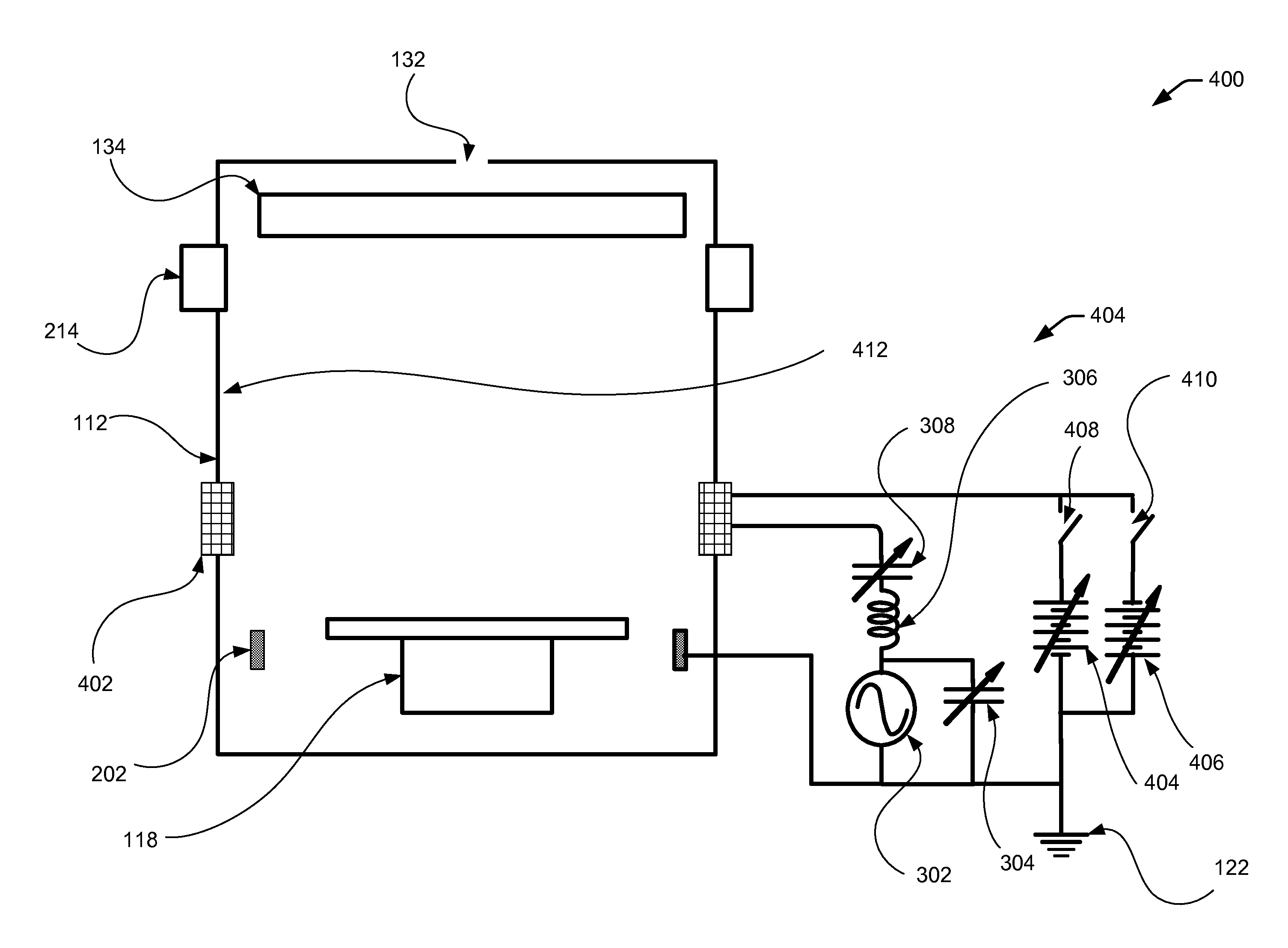
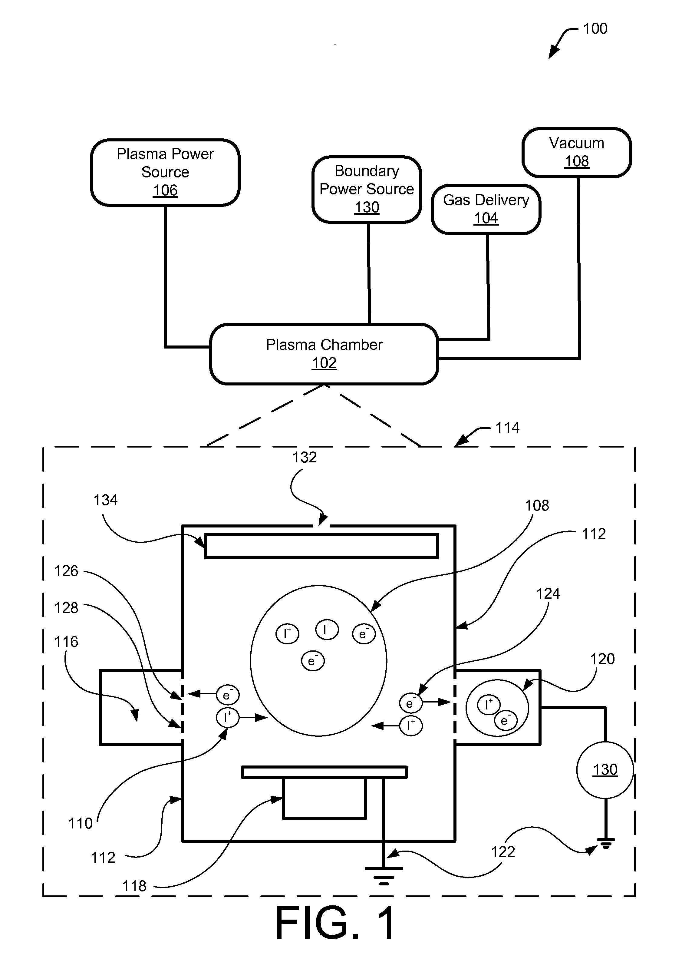
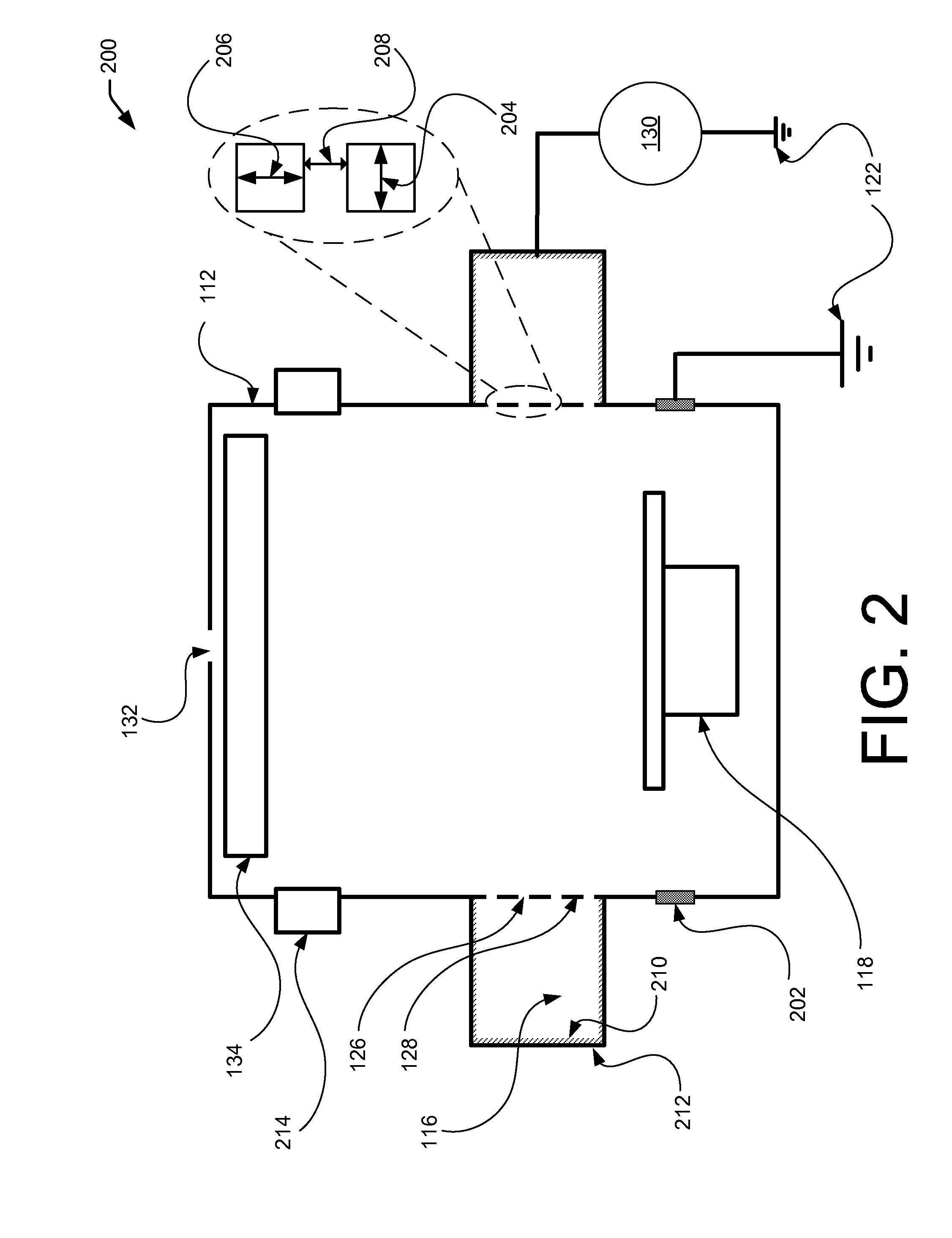
This patent describes a method for minimizing loss of charged particles (such as ions) in a plasma chamber. The method involves altering the boundary potential near the chamber wall to push or diffuse ions away from the wall. This is done by creating a ring cavity around the chamber wall and applying a potential difference to it. This creates a more uniform plasma density across the chamber, reducing the loss of charged particles and improving substrate processing uniformity. The method is achieved using non-ambipolar diffusion of ions and electrons between different plasma regions. Overall, this patent aims to improve the efficiency and stability of plasma processing.

Problems solved by technology

The loss of the charge particles to a potential boundary or chamber wall may result in plasma density non-uniformity that leads to substrate processing non-uniformity.

Method used


Image

  • Non-ambipolar electric pressure plasma uniformity control
  • Non-ambipolar electric pressure plasma uniformity control
  • Non-ambipolar electric pressure plasma uniformity control

Examples


Embodiment Construction

[0017]The following Detailed Description refers to accompanying drawings to illustrate exemplary embodiments consistent with the present disclosure. References in the Detailed Description to “one embodiment,”“an embodiment,”“an exemplary embodiment,” etc., indicate that the exemplary embodiment described can include a particular feature, structure, or characteristic, but every exemplary embodiment does not necessarily include the particular feature, structure, or characteristic. Moreover, such phrases are not necessarily referring to the same embodiment. Further, when a particular feature, structure, or characteristic is described in connection with an embodiment, it is within the knowledge of those skilled in the relevant art(s) to affect such feature, structure, or characteristic in connection with other exemplary embodiments whether or not explicitly described.

[0018]The exemplary embodiments described herein are provided for illustrative purposes, and are not limiting. Other embo...


PUM

PropertyMeasurementUnit
Electric potential / voltageaaaaaaaaaa
Dielectric polarization enthalpyaaaaaaaaaa
Densityaaaaaaaaaa

Abstract

This disclosure relates to a plasma processing system for controlling plasma density near the edge or perimeter of a substrate that is being processed. The plasma processing system may include a plasma chamber that can receive and process the substrate using plasma for etching the substrate, doping the substrate, or depositing a film on the substrate. This disclosure relates to a plasma processing system that may be configured to enable non-ambipolar diffusion to counter ion loss to the chamber wall. The plasma processing system may include a ring cavity coupled to the plasma processing system that is in fluid communication with plasma generated in the plasma processing system. The ring cavity may be coupled to a power source to form plasma that may diffuse ions into the plasma processing system to minimize the impact of ion loss to the chamber wall.

Description

CROSS REFERENCE TO RELATED APPLICATION[0001]Pursuant to 37 C.F.R. §1.78(a)(4), this application claims the benefit of and priority to prior filed co-pending Provisional Application Ser. No. 61 / 799,718 filed Mar. 15, 2013, which is expressly incorporated herein by reference.FIELD OF THE INVENTION[0002]This invention relates to semiconductor processing technology, and more particularly, to apparatus and methods for controlling plasma properties of a processing system for treating a substrate.BACKGROUND OF THE INVENTION[0003]Plasma uniformity control during plasma processing for treating semiconductor substrates is important to achieve patterning structures on a substrate or controlling the amount of material removed from or deposited on or into the substrate. A plasma processing system may include a large distance or gap between the plasma source and the substrate. A chamber wall of the plasma processing may be disposed between the plasma source and the substrate. As a result, ions an...

Claims


Application Information

Patent Timeline
IPC IPC(8): H01L21/263
CPCH01L21/263H01J37/32568H01J37/32697H01J37/32431H01L21/67069
Inventor CHEN, LEECHEN, ZHIYINGZHAO, JIANPINGFUNK, MERRITT
Owner TOKYO ELECTRON LTD
Learn More