
Process and installation for pyrolysis of a product in the form of divided solids, in particular polymer waste

a technology of divided solids and pyrolysis gas, which is applied in the production of liquid hydrocarbon mixtures, special form destructive distillation, coking carbonaceous materials, etc., can solve the problems of limited yield, low yield, and the above-mentioned document does not enable the extraction of pyrolysis gas with a high methane content, so as to improve the efficiency of pyrolysis and improve the methane content of the pyrolysis gas

Inactive Publication Date: 2014-09-25
LEPEZ CONSEILS FINANCE INNOVATIONS LCFI
View PDF4 Cites 11 Cited by
  • Summary
  • Abstract
  • Description
  • Claims
  • Application Information

AI Technical Summary

Benefits of technology

The patent describes a method for upgrading pyrolysis gas produced from a polymeric substance by using liquefaction to increase the yield of the installation. The use of liquefaction means allows for the substance to be in liquid form when introduced into the reactor, leading to advantages such as increased yield and simplified connection between the preconditioning device and the reactor without any risk of oxidation. The temperature of the liquefied substance is also important, with the optimal condition being high enough to prevent excessive cooling and blocking of the reactor. As a result, the method provides a way to obtain methane contents greater than 40% in the pyrolysis gas.

Problems solved by technology

When used more particularly with polymeric waste such as plastics materials, rubbers, and / or elastomers, it has been found that the yield of the treatment recommended in the above-mentioned document does not enable pyrolysis gas to be obtained that has a high methane content.
In addition, the density of the treated substances remains low at the beginning of their treatment, thus leading to limited yields.

Method used


Image

  • Process and installation for pyrolysis of a product in the form of divided solids, in particular polymer waste
  • Process and installation for pyrolysis of a product in the form of divided solids, in particular polymer waste

Examples


Embodiment Construction

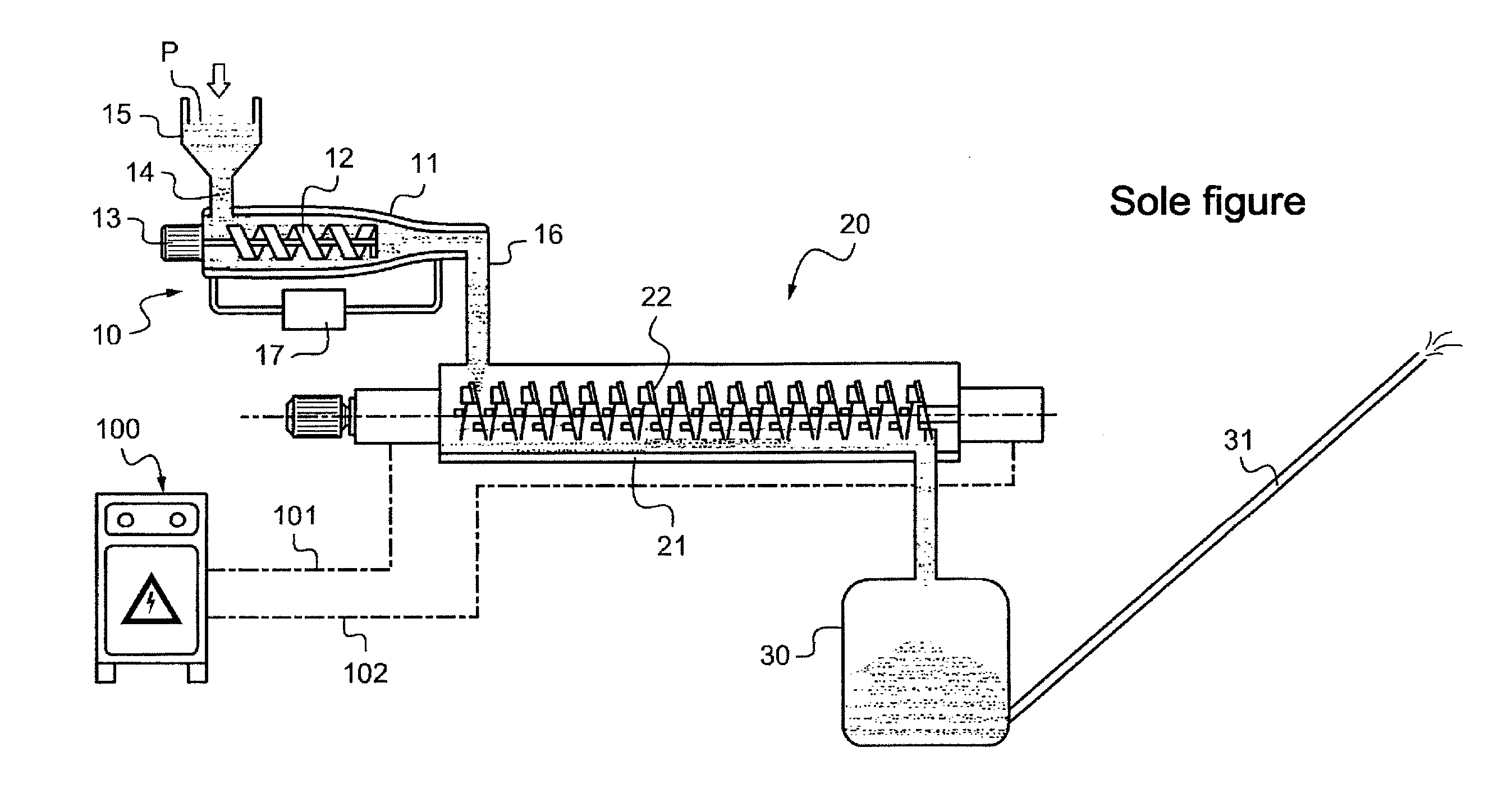
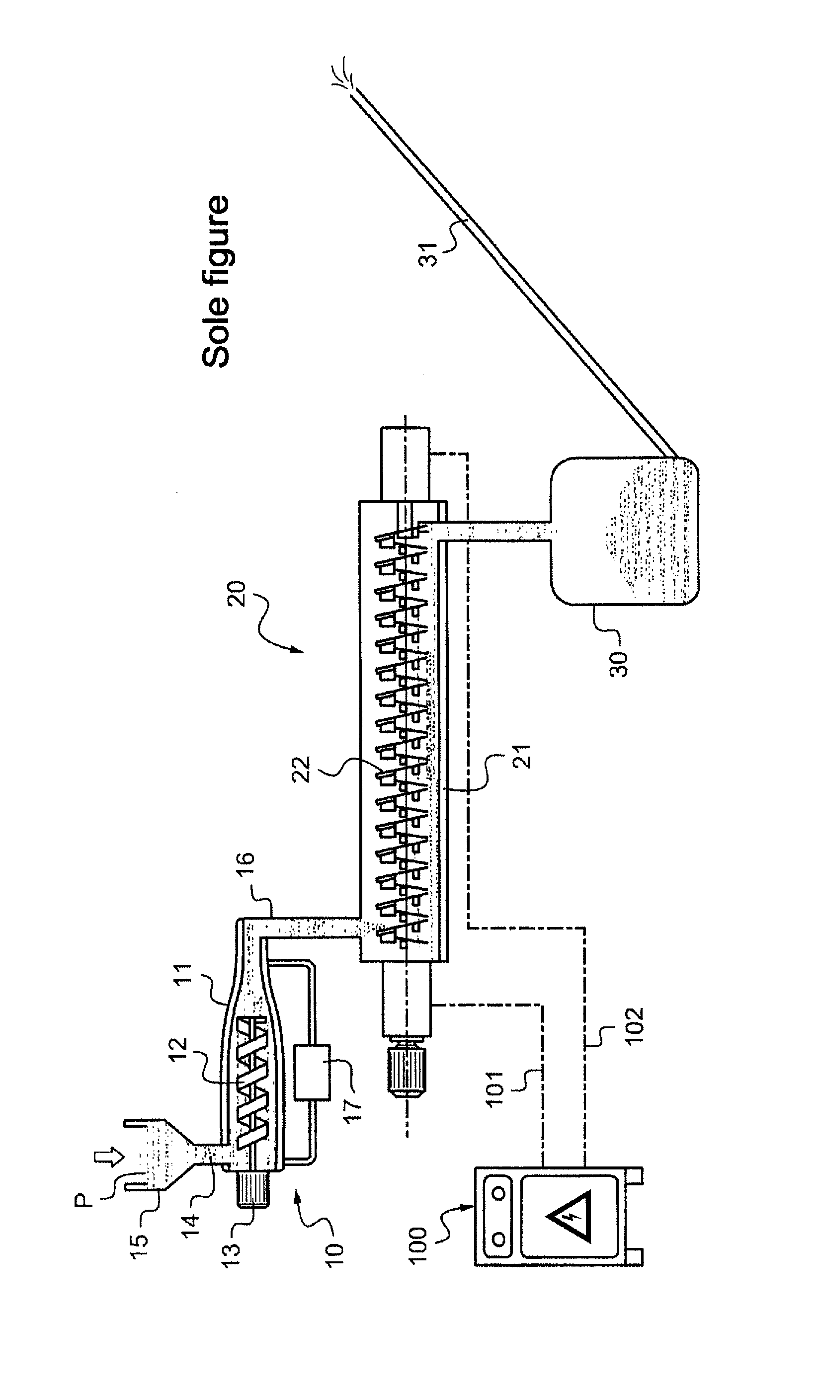
[0022]The FIGURE is a diagrammatic view of an installation for processing a substance in the form of divided solids, in particular polymeric solids such as plastics, rubber, or elastomer waste. It may be household waste, industrial waste, or indeed substances that have previously been micronized.

[0023]In general, the substances concerned are divided solids capable of producing in particular pyrolytic oils by recondensation of gas when the substances are pyrolyzed at temperatures lying in the range 400° C. to 600° C., which oils have energy or chemical content that is suitable for recycling, and the pyrolysis gas also contains components (such as methane, hydrogen, acetylene, . . . ) that are industrially advantageous when the substances are pyrolyzed at temperatures in the range 600° C. to 900° C.

[0024]The substance for treatment, referenced P, is initially inserted into a preconditioning device 10 enabling the substance to be compacted and heated so as to liquefy it before it is in...


PUM


Abstract

An installation for pyrolyzing divided solids, such as waste plastics, rubbers, or elastomers. The installation has a device for making divided solids suitable for facilitating pyrolysis by a pyrolysis reactor. The reactor inlet is leak-tightly connected to the preconditioning device and has at least one heating transfer member for transferring the divided solids within the reactor while also pyrolyzing the solids. The member is a conveyor screw or a vibrating tube, and being made of a material that is associated with means for heating it by the Joule effect. The preconditioning device includes liquefaction means for bringing the substance to the outlet of the preconditioning device in a liquid state at an outlet temperature, and a regulator for regulating the temperature of the substance at the outlet from the preconditioning device as a function of a temperature representative of an inlet temperature of the reactor.

Description

[0001]The present invention relates to pyrolyzing a substance in the form of divided solids, in particular polymeric waste such as waste plastics materials, rubbers, and / or elastomers.BACKGROUND OF THE INVENTION[0002]Proposals are made in Document WO 2010 / 128055A1 for an installation for pyrolyzing a substance in the form of divided solids and comprising:[0003]a preconditioning device comprising a double-wall auger having a metering screw and associated with a flow of hot liquid between the walls for enabling the substance to be brought to a state that is suitable for facilitating pyrolysis thereof; and[0004]a pyrolysis reactor having an inlet connected in leaktight manner to the outlet of the preconditioning device and fitted with at least one heating transfer member for transferring the substance from the inlet to an outlet of the reactor while also pyrolyzing the substance, the member being for example in the form of a conveyor screw or a vibrating tube, and being made of a mater...

Claims


Application Information

Patent Timeline
IPC IPC(8): C10B7/10
CPCC10B7/10C10B19/00C10B53/07C10G1/10Y02E50/10Y02P20/143
Inventor LEPEZ, OLIVIER
Owner LEPEZ CONSEILS FINANCE INNOVATIONS LCFI
Learn More