Chemical vapour deposition injector

a technology of injector and vapour, which is applied in the direction of liquid spraying apparatus, coating, metal material coating process, etc., can solve the problems of degrading the reactor, difficult maintenance, and none can meet these challenges in a cost effective way, so as to improve the circulation gas flow, reduce the turbulence of gas flow, and improve the circulation of second gas

Inactive Publication Date: 2014-09-25
ASM TECH SINGAPORE PTE LTD
View PDF5 Cites 21 Cited by
  • Summary
  • Abstract
  • Description
  • Claims
  • Application Information

AI Technical Summary

Benefits of technology

[0013]An advantage of the described embodiment is that this achieves a more uniform flow rate for the gases and much easier to manufacture. Further, the arrangement ensures that the two gases do not mix until the gases reach the reaction chamber.
[0015]Each of the discrete first and second conduits may include a flow development portion for reducing pressure of the first and second gas respectively as the gases exits to the reaction chamber. The development portion may have an opening for receiving the first or second gas and a discharge opening for discharging the first or second gas to the reaction chamber, wherein the discharge opening is larger than the first opening. The flow development portion is particularly advantageous to reduce turbulence of the gas flow.
[0016]The gas injector body may further comprise the first plenum and the second plenum. The gas injector body may further comprise a first gas distribution channel for receiving the first gas from a first gas inlet and the first gas distribution channel is arranged adjacent to and around the first gas plenum. The gas injector body may further comprise a first plenum wall separating the first gas distribution channel and the first gas plenum, and with the first plenum wall comprising a first continuous gap to enable the first gas to diffuse from the first gas distribution channel to the first gas plenum. In this way, this improves the circulation gas flow. The gap may be about 1 mm for optimum results but it should be appreciated that this dimension may be varied.
[0017]The gas injector may also comprise a second gas distribution channel for receiving the second gas from a second gas inlet, and the second gas distribution channel is arranged adjacent to and around the second gas plenum. The gas injector may further comprise a second plenum wall separating the second gas distribution channel and the second gas plenum, and with the second plenum wall comprising a second continuous gap to enable the second gas to diffuse from the second gas distribution channel to the second gas plenum. In this way, circulation of the second gas is improved. The gap may be about 1 mm for optimum results but it should be appreciated that other dimensions are possible too.

Problems solved by technology

A first challenge in the design of the gas injector is to prevent pre-reaction between the two precursors.
Such condensation is a waste of the precursors and may also degrade the reactor.
A second challenge is to achieve uniform flow rates for the two precursors as the gases leave the gas injector's outlets.
However, most address one but not the other challenges and for those that attempt to address both of these challenges, none can meet these challenges in a cost effective way or they are difficult to maintain.

Method used


Image

  • Chemical vapour deposition injector
  • Chemical vapour deposition injector
  • Chemical vapour deposition injector

Examples


Embodiment Construction

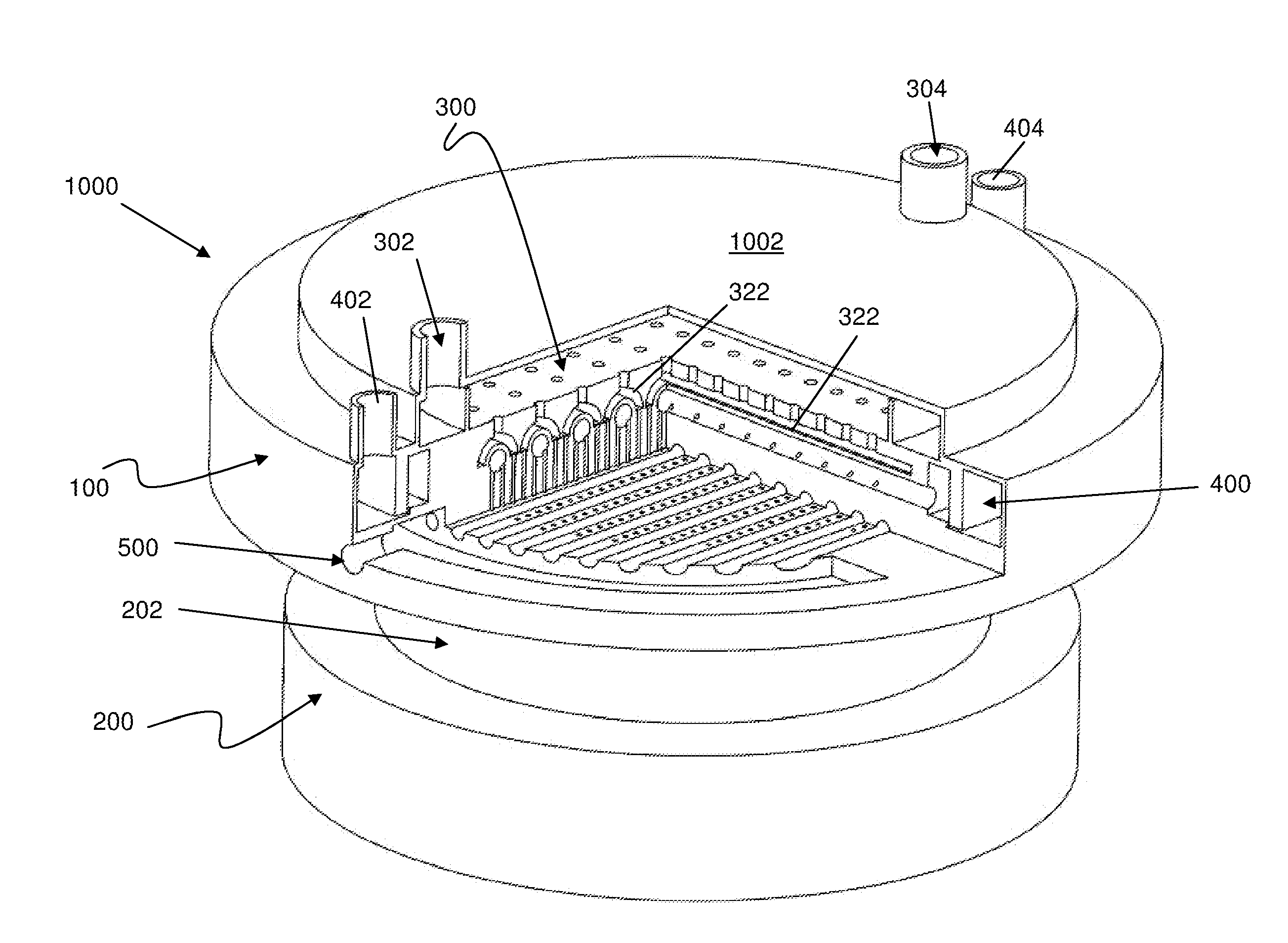
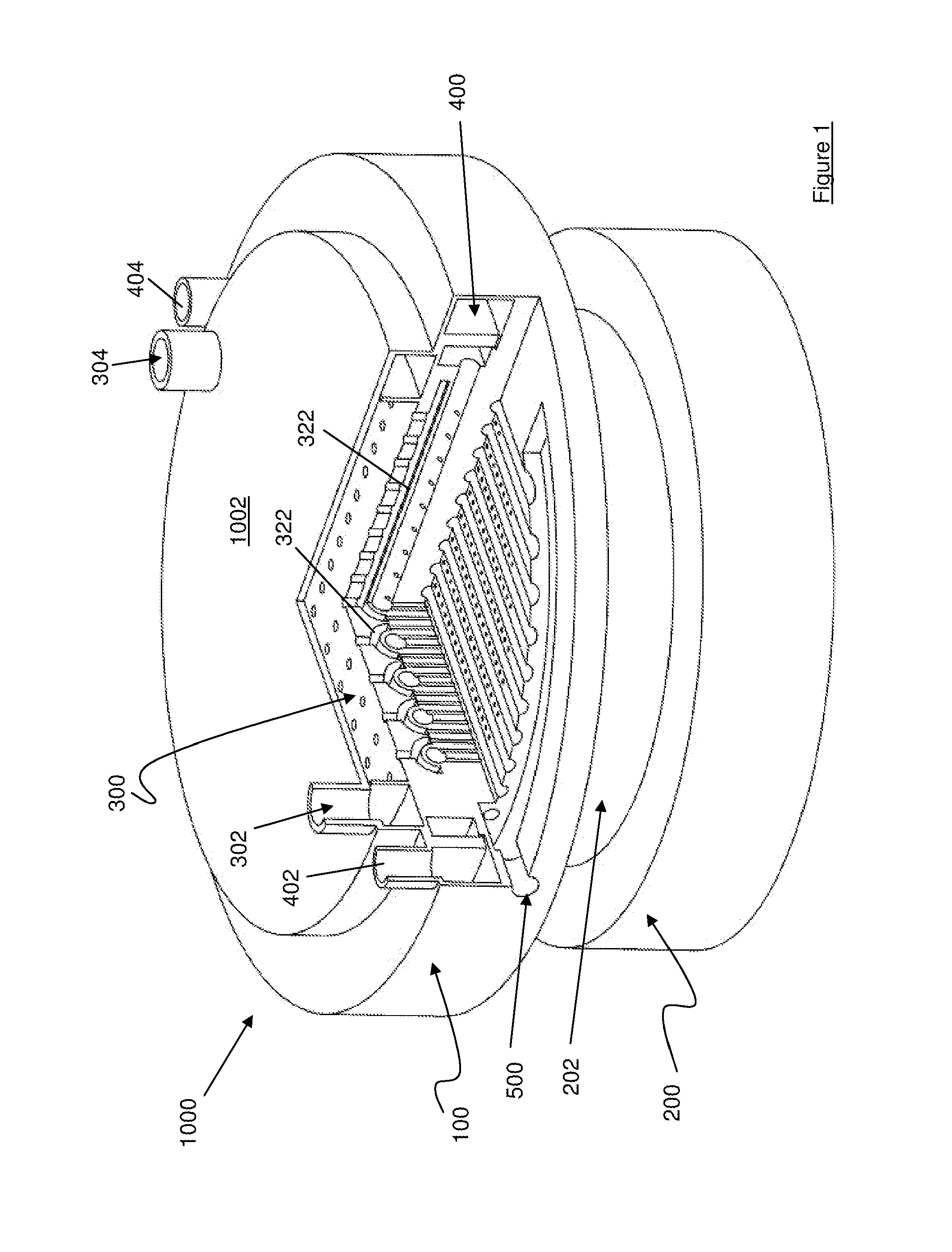
[0034]FIG. 1 is a perspective view of a chemical vapour deposition (CVD) reactor 1000 which comprises a gas injector 100 and a deposition compartment 200, which includes a reaction chamber 202. In FIG. 1, part of the reactor 1000 is omitted to show first, second and third fluid input and delivery members 300,400,500 of the gas injector 100.

[0035]The first and second gas input and delivery members 300,400 are arranged to deliver and channel a first precursor gas and a second precursors respectively to the reaction chamber 202 and the third fluid input and delivery member 500 is arranged to deliver a heat exchanging fluid for controlling temperature of the first and second gas input and delivery members 300,400.

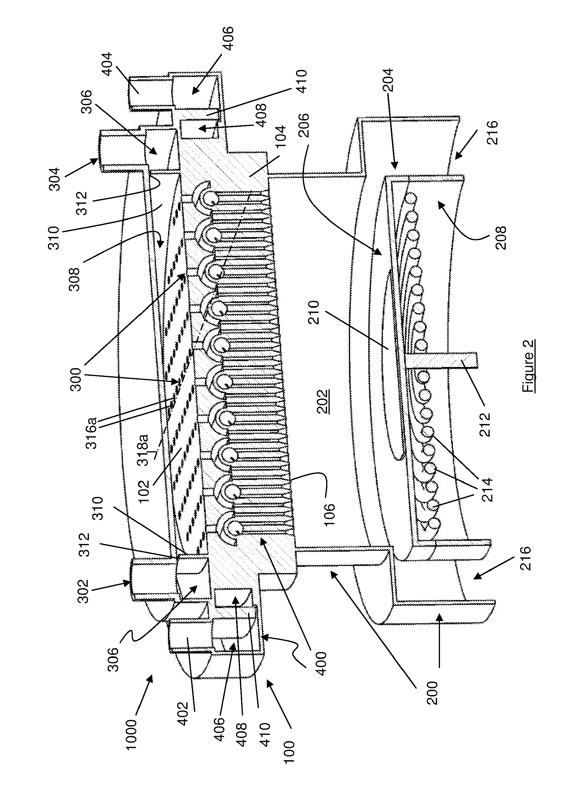
[0036]FIG. 2 is a cross-sectional perspective view of the CVD reactor 1000 to show the first and second gas input delivery members 300,400 and the deposition compartment 200. The reactor 1000 further includes a substrate support assembly 204 located within the deposition chambe...


PUM

PropertyMeasurementUnit
centre-to-centre distanceaaaaaaaaaa
diameteraaaaaaaaaa
heightaaaaaaaaaa

Abstract

Disclosed is a chemical vapour deposition injector 100, comprising a gas injector body 104 having a plurality of holes for directing a first gas from a first gas plenum into respective first gas channels of the gas injector body, each first gas channel extending in a first direction and arranged to branch into separate flow paths; a plurality of discrete first conduits, each first conduit being arranged to connect to a respective one of the discrete flow paths for carrying the first gas to a reaction chamber; a second gas channel for directing a second gas from a second gas plenum into the gas injector body, the second gas channel having a longitudinal axis which extends in a second direction transverse to the first direction; and a plurality of discrete second conduits coupled to the second gas channel and arranged to carry the second gas from the second gas channel to the reactor chamber; wherein at least some of the discrete second conduits are arranged between the discrete first conduits.

Description

BACKGROUND AND FIELD[0001]This invention relates to a chemical vapour deposition injector.[0002]Chemical vapour deposition (CVD) reactors, or more particularly metal organic chemical deposition (MOCVD) reactors are used in semiconductor industry to produce compound semiconductor devices such as laser diodes, light emitting diodes (LEDs) etc. Such reactors include a reaction chamber where precursors react with each other under certain temperature and pressure conditions to form a homogeneous gas mixture which is deposited as a thin film on a substrate placed in the reaction chamber.[0003]For MOCVD, the two precursors are typically TMGa (or TMIn) and NH3 The reactor includes a gas injector for introducing the precursors into the reaction chamber. A first challenge in the design of the gas injector is to prevent pre-reaction between the two precursors. This is because if they are allowed to mix before entering the reaction chamber, the two precursors would mix and react with each other...

Claims


Application Information

Patent Timeline
Patent Type & Authority Applications(United States)
IPC IPC(8): C23C16/455
CPCC23C16/45565
Inventor KUAH, TENG HOCKLIU, HONGBOWEI, JIUANWANG, WENTAOCHEN, JINGSHENGDING, JIAPEIRAGHAVENDRA, RAVINDRAJOTHEESWARAN, BUBESH BABUHASSAN, MEER SAIFUL
Owner ASM TECH SINGAPORE PTE LTD
Why Eureka
Try Eureka