Power generation apparatus and power generation system

Active Publication Date: 2014-09-25
KOBE STEEL LTD
View PDF25 Cites 2 Cited by
  • Summary
  • Abstract
  • Description
  • Claims
  • Application Information

AI Technical Summary

Benefits of technology

[0016]As described above, according to the present invention, it is possible to suppress the working medium cir

Problems solved by technology

Further, since the working medium does not flow inside the generator or slightly flows inside the generator, there is a low

Method used


Image

  • Power generation apparatus and power generation system
  • Power generation apparatus and power generation system
  • Power generation apparatus and power generation system

Examples


Embodiment Construction

Hereinafter, an embodiment of the present invention will be described in detail with reference to the drawings.

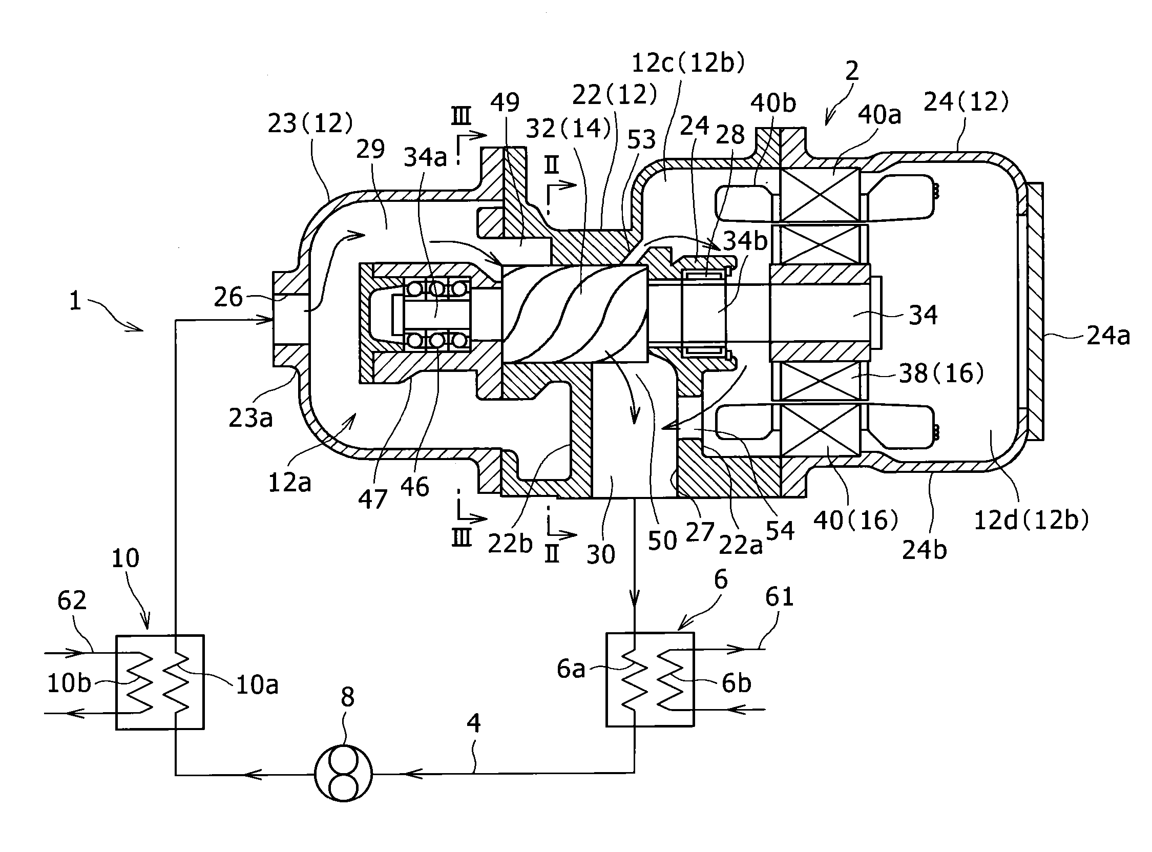
[0022]As illustrated in FIG. 1, a power generation system 1 according to the embodiment is a power generation system that uses a Rankine cycle, and includes a power generation apparatus 2, a condenser 6, a circulation pump 8, and an evaporator 10. The power generation apparatus 2, the condenser 6, the circulation pump 8, and the evaporator 10 are provided in a circulation flow passage 4 in this order. A working medium circulates in the circulation flow passage 4. As the working medium, for example, a cooling medium such as R245fa (1, 1, 1, 3, 3-Pentafluoropropane) having a low boiling point is used. Accordingly, the power generation system is of a binary power generation type that recovers power from the low-temperature waste heat. Furthermore, the power generation system is configured as an on-vehicle system.

[0023]The power generation apparatus 2 includes a screw-type expa...


PUM


Abstract

A power generation apparatus according to the present invention includes: an expander; a generator that includes a generator rotor driven by the expander and a stator disposed outside the generator rotor in the radial direction; and a casing that includes an expander chamber accommodating the expander and a generator chamber accommodating the generator. The casing includes a first communication portion that causes an expansion chamber which gradually expands a working medium by the expander in the expander chamber to communicate with a front generator portion which is located nearer the expansion chamber than the generator in the generator chamber and a second communication portion that causes a portion which is a downstream portion from the expansion chamber and is located near the expansion chamber with respect to the generator to communicate with the front generator portion.

Description

BACKGROUND OF THE INVENTION[0001]1. (Field of the Invention)[0002]The present invention relates to a power generation apparatus and a power generation system.[0003]2. (Description of the Related Art)[0004]Hitherto, there is known a power generation apparatus that drives an expander by a working medium and generates power by a generator directly coupled to the expander. A power generation apparatus disclosed in JP 2004-353571 A is equipped with a cooling pipe that leads a working medium condensed by a condenser to a cooler of a generator. Accordingly, the generator may be effectively cooled. However, a problem arises in that the cooling pipe that leads the working medium to the cooler of the generator is needed. On the contrary, a power generation apparatus disclosed in JP 2012-147567 A may cool a generator without providing a cooling pipe. That is, in the power generation apparatus, the expander and the generator are accommodated inside a casing, and the casing is provided with a pa...

Claims


Application Information

Patent Timeline
IPC IPC(8): F15B15/20H02K99/00
CPCH02K57/003F15B15/20F01C1/16F01C13/00H02K99/10F01C21/06
Inventor TSUBOI, NOBORU
Owner KOBE STEEL LTD
Why Eureka
Try Eureka