

On-board radar apparatus
a radar and apparatus technology, applied in the direction of antennas, instruments, measurement devices, etc., can solve the problems of increasing the cost of the lens antenna, the volume of the lens antenna b>900/b> becomes large, and it is difficult to apply the lens antenna to consumer products, so as to achieve high accuracy without increasing the size and cost of the radar apparatus
- Summary
- Abstract
- Description
- Claims
- Application Information
AI Technical Summary
Benefits of technology
Problems solved by technology
Method used
Image

Examples
first embodiment
[0037]Hereinafter, embodiments of the invention will be described with reference to the accompanying drawings.
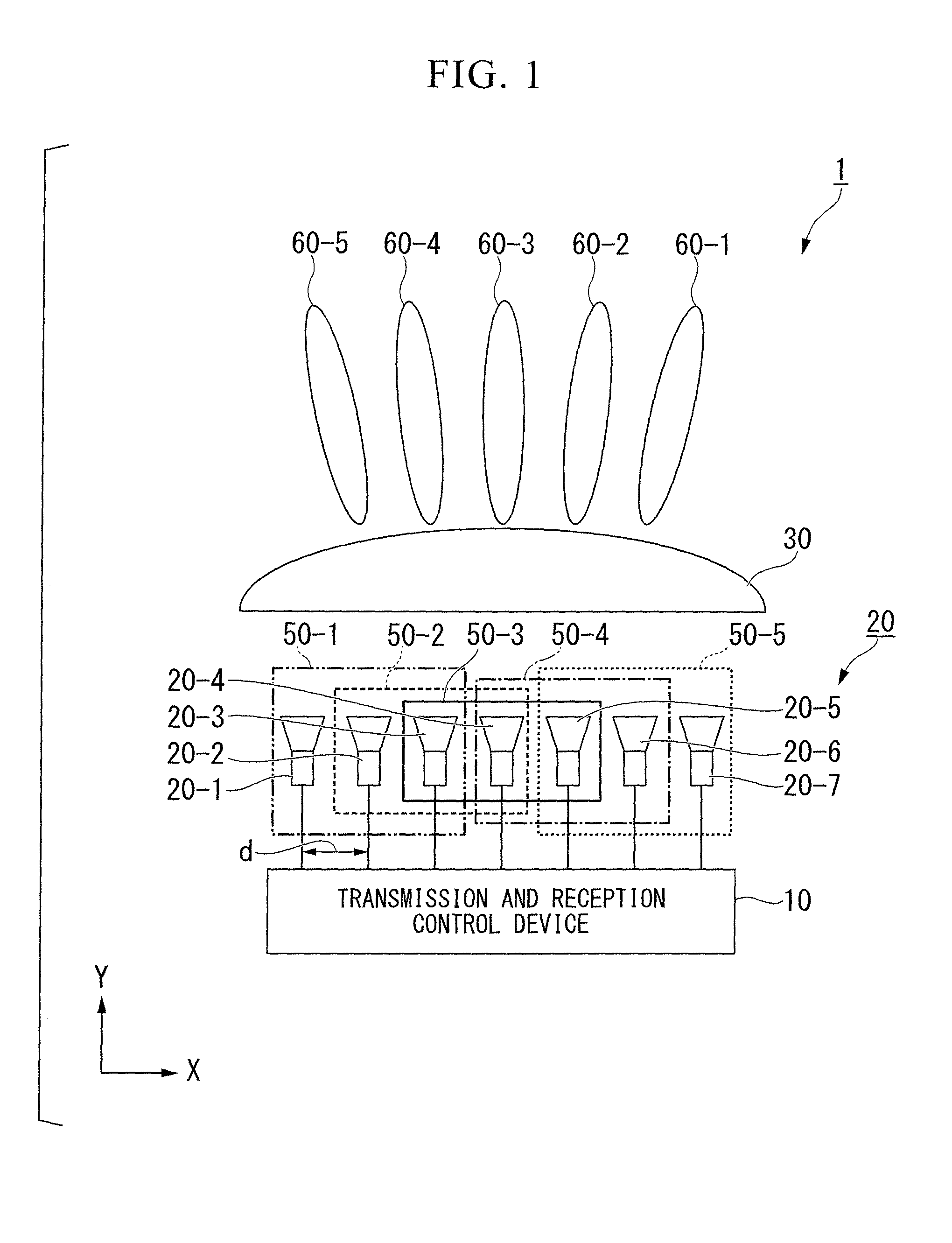
[0038]FIG. 1 is a diagram schematically illustrating a configuration of a radar apparatus 1 according to a first embodiment. As shown in FIG. 1, the radar apparatus 1 includes a transmission and reception control device 10, an antenna unit 20, and a lens 30. In FIG. 1, a transverse direction on the paper plane is referred to as an x-axis direction, and a longitudinal direction on the paper plane is referred to as a y-axis direction.
[0039]The transmission and reception control device 10 distributes a transmission signal that is generated inside, and controls the phase and amplitude of the distributed transmission signal to supply the result to each of antenna elements 20-1 to 20-7. Furthermore, the transmission and reception control device 10 performs detection of an object based on a reception signal received by each of the antenna elements 20-1 to 20-7.
[0040]The antenna uni...
second embodiment
[0122]In a second embodiment, a case where a bifocal lens having different beam widths is used as a lens of a radar apparatus will be described.
[0123]FIG. 11 is a diagram illustrating an example of a bifocal lens 30b according to the second embodiment.
[0124]An upper part in FIG. 11 represents a top view of the bifocal lens 30b, and a lower part in FIG. 11 represents a side view of the bifocal lens 30b.
[0125]As shown in FIG. 11, the bifocal lens 30b is configured so that a wide angle beam lens 31b of an elliptical shape is disposed at the center thereof, and a high-gain lens 32b with a large horizontal width is formed on the outside thereof.
[0126]FIG. 12 is a diagram schematically illustrating a configuration of a radar apparatus 1b that uses the bifocal lens 30b according to the second embodiment. As shown in FIG. 12, the radar apparatus 1b includes a transmission and reception control device 10, an antenna unit 20b, and the bifocal lens 30b. The configuration of the transmission a...
third embodiment
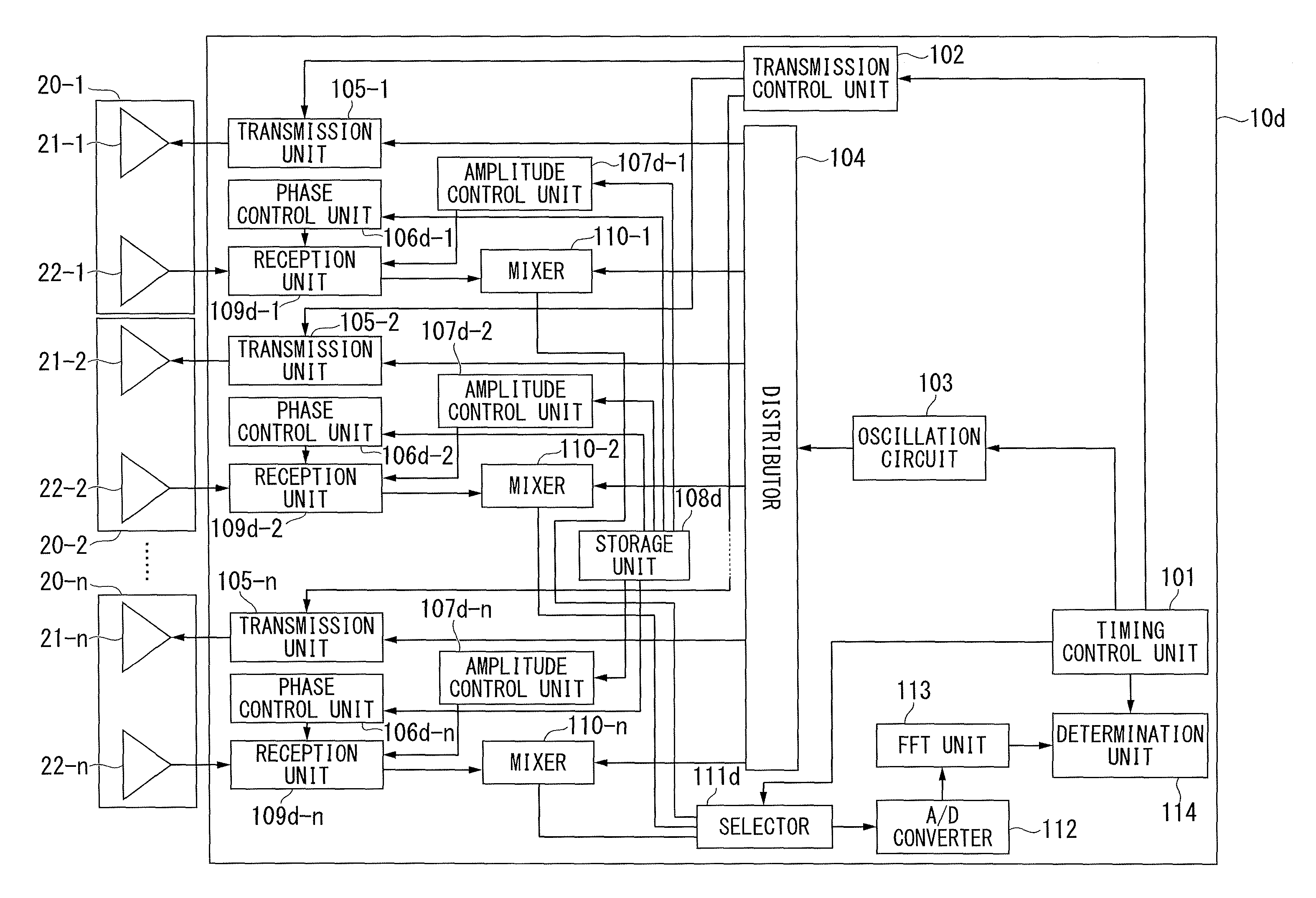
[0143]In a third embodiment, an example in which a control is performed so that a peak of a side lobe in an antenna pattern and a null point overlap each other as a phase control unit 106d-n controls the phase and an amplitude control unit 107d-n controls the amplitude for the reception antenna (see FIG. 2) will be described.
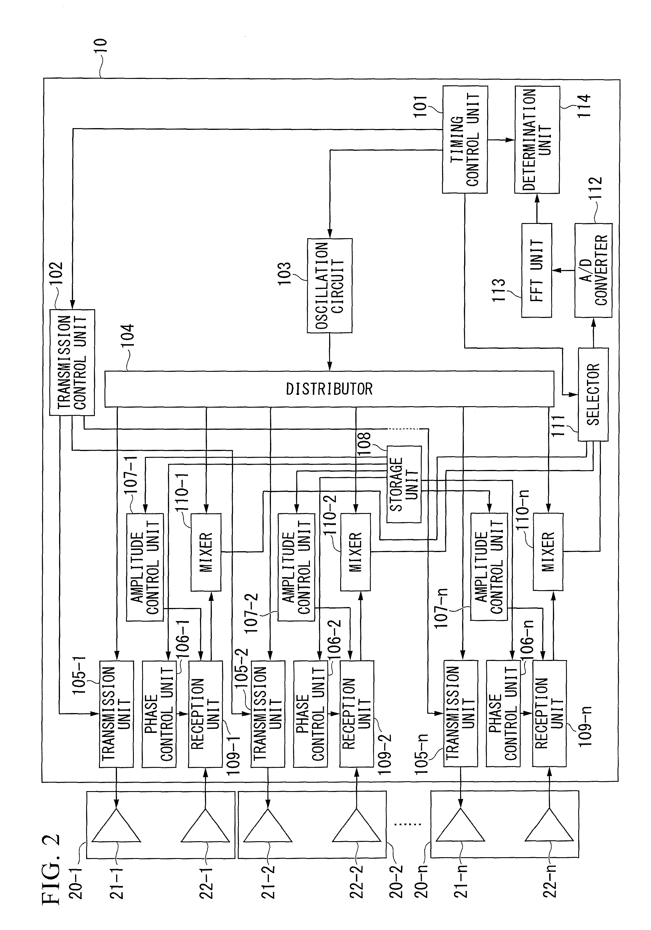
[0144]FIG. 15 is a block diagram illustrating a configuration of a transmission and reception control device 10d according to the third embodiment. The same reference numerals are given to functional units having the same functions as in FIG. 2, and description thereof will not be repeated. The transmission and reception control device 10d according to the third embodiment is different from the device shown in FIG. 2 in the phase control unit 106d-n, the amplitude control unit 107d-n, a storage unit 108d, a reception unit 109d-n and a selector 111d.
[0145]The phase control unit 106d-n reads a phase weight for reception stored in the storage unit 108d, and contro...
PUM
 Abstract
Description
Claims
Application Information