Capacitor Device and Electrical Power Conversion Device

a technology of capacitors and capacitor elements, applied in the direction of fixed capacitors, dc-ac conversion without reversal, fixed capacitor details, etc., can solve the problem of insufficient cooling of film capacitor elements, achieve enhanced heat dissipation performance, enhance heat dissipation performance, and high thermal conductivity

Active Publication Date: 2014-09-25
HITACHI LTD
View PDF1 Cites 37 Cited by
  • Summary
  • Abstract
  • Description
  • Claims
  • Application Information

AI Technical Summary

Benefits of technology

[0010]With the capacitor device described in the above Patent Document, the characteristic for dissipation of heat to the case is enhanced by charging the resin material that has high thermal conductivity into the gap between that one of the electrodes, among the two electrodes on opposite sides of the film capacitor element, that faces the bottom surface of the case and a portion of the outer circumferential surface of the wound up film capacitor element, and the inner surface of the bottom of the case. However, with the capacitor device described in the above Patent Document, the enhancement of the performance for dissipation of heat generated within the film capacitor element to the case only relates to that electrode at one of its sides, among the two electrodes at the two sides of the film capacitor element, from both of which it would be desirable to dissipate heat. Due to this, there is a danger that the cooling of the film capacitor element will not be sufficient.

Problems solved by technology

Due to this, there is a danger that the cooling of the film capacitor element will not be sufficient.

Method used


Image

  • Capacitor Device and Electrical Power Conversion Device
  • Capacitor Device and Electrical Power Conversion Device
  • Capacitor Device and Electrical Power Conversion Device

Examples


embodiment # 1

Embodiment #1

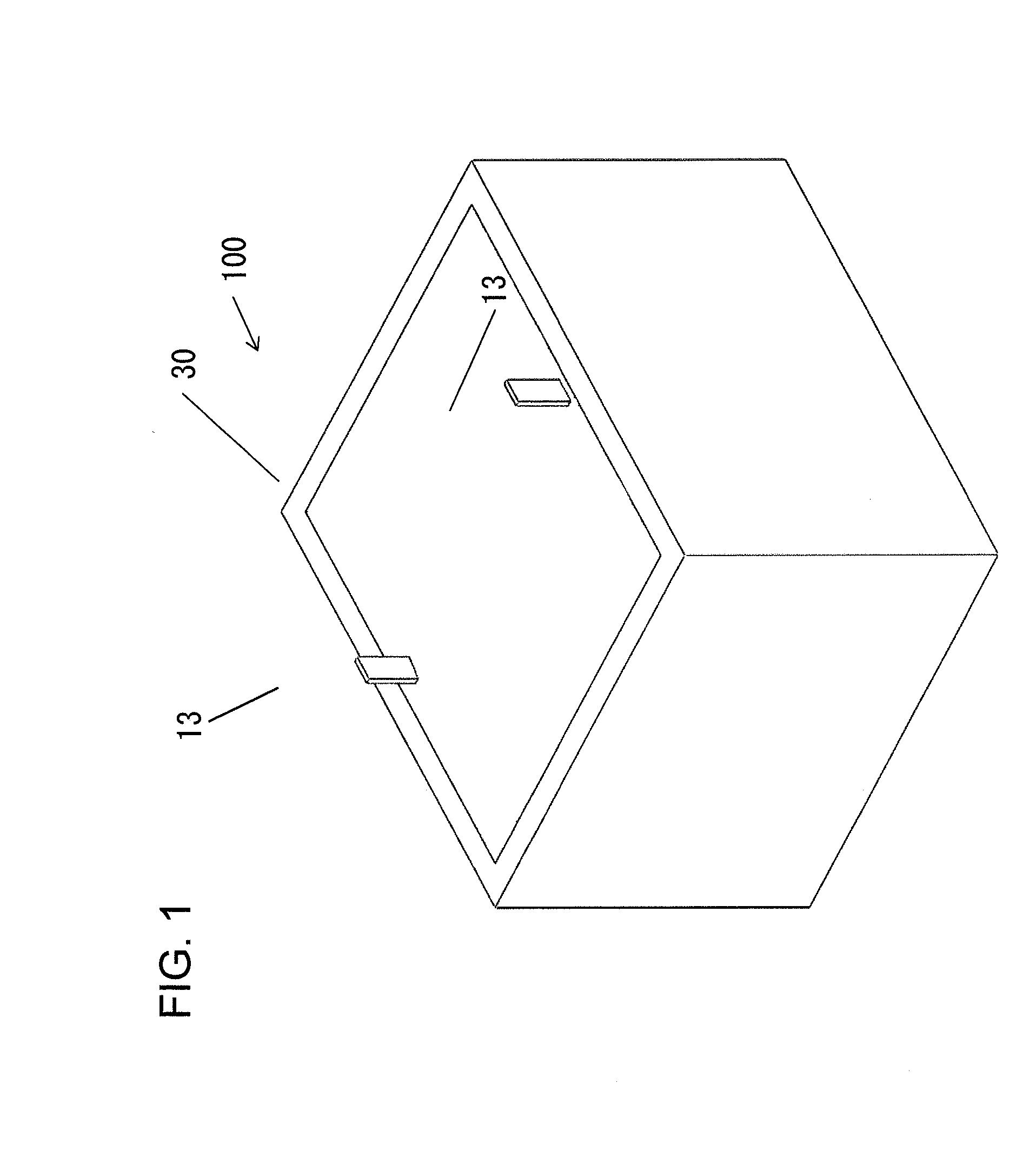
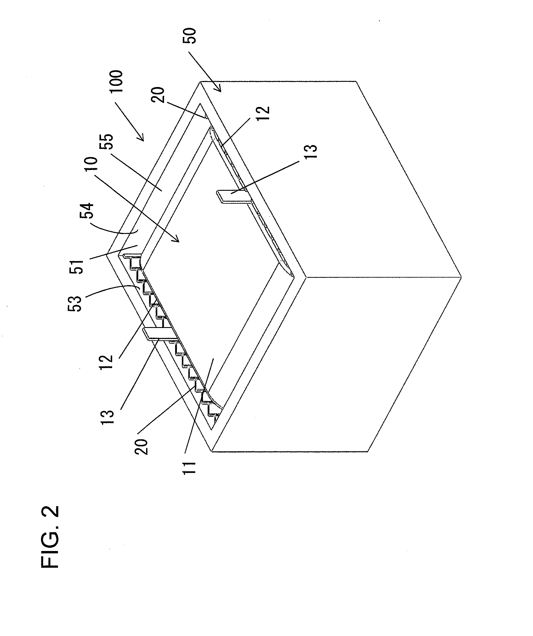
[0030]First embodiments of a capacitor device and of an electrical power conversion device according to the present invention will now be explained with reference to FIGS. 1 through 5. FIG. 1 is an external view of the capacitor device 100 according to the first embodiment, and FIG. 2 is a figure showing the situation in the interior of this capacitor device 100. Moreover, FIG. 3 is an exploded diagram showing the capacitor device 100, and FIGS. 4A and 4B are figures schematically showing cross sections of the capacitor device 100. This capacitor device 100 is a component that is employed, for example, for smoothing DC power produced by an electrical power conversion device that is used in a HEV (hybrid electric vehicle) or an EV (electric vehicle) or the like. A capacitor like this is called a DC-link capacitor.

[0031]The capacitor device 100 comprises a film capacitor element 10, a case 50 made from metal that contains the film capacitor element 10, two resin sheets (i...

embodiment # 2

Embodiment #2

[0048]Referring to FIGS. 6A, 6B and 7, a capacitor device and an electrical power conversion device according to a second embodiment of the present invention will now be explained. In the following explanation, to structural elements that are the same as in the first embodiment, the same reference symbols are appended, and the explanation will principally focus upon the points of difference. Features that are not particularly explained are the same as in the first embodiment. In this embodiment, principally, the aspect that is different from the first embodiment is the feature that, instead of performing positional determination of the film capacitor element 10 by taking advantage of the resilience of the inserts 20, positional determination of the film capacitor element 10 is performed by forming opposing inner walls 57, 57 as inclined, and by also forming the inserts 60 in the shape of tapers or wedges, so that they are engaged with each other.

[0049]FIGS. 6A and 6B ar...

embodiment # 3

Embodiment #3

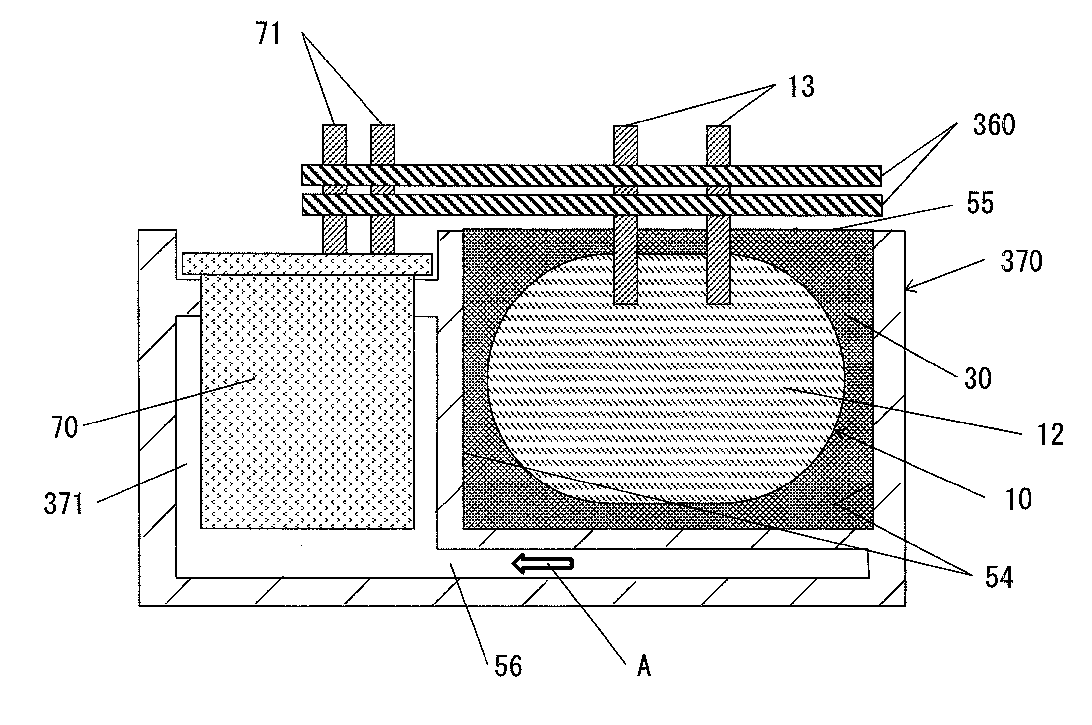
[0066]Referring to FIGS. 8 through 12, a capacitor device and an electrical power conversion device according to a third embodiment of the present invention will now be explained. In the following explanation, to structural elements that are the same as in the first and second embodiments, the same reference symbols are appended, and the explanation will principally focus upon the points of difference. Features that are not particularly explained are the same as in the first and second embodiments. In this embodiment, principally, the aspect that is different from the first and the second embodiments is the feature that a film capacitor element and a power semiconductor module are received within the same case and function together as an electrical power conversion device.

[0067]The electrical power conversion device of this embodiment is not limited to application in a hybrid automobile (i.e. an HEV); it can also be applied as an electrical power conversion device to be...


PUM


Abstract

A capacitor device includes: a film capacitor element that comprises a coiled body in which an insulating layer and an electrification layer are laminated and wound together, and a pair of collector electrodes that are formed upon two opposite end faces of the coiled body; a case that comprises a capacitor housing portion within which the film capacitor element is received; a pair of inserts having insulation properties, one of which is inserted between one of the pair of collector electrodes and one of inner walls of the capacitor housing portion; and a mass of sealing and insulating material that is charged between the film capacitor element and the one of the inner walls of the capacitor housing portion.

Description

INCORPORATION BY REFERENCE[0001]The disclosure of the following priority application is herein incorporated by reference: Japanese Patent Application No. 2013-060494, filed Mar. 22, 2013.BACKGROUND OF INVENTION[0002]1. Field of the Invention[0003]The present invention relates to a capacitor device and to an electrical power conversion device.[0004]2. Description of Related Art[0005]For some years now, the market for hybrid automobiles (HEV: Hybrid Electric Vehicle) and for electric automobiles (EV: Electric Vehicle) has seen rapid spread and development, and as a result there have been greater and greater demands upon electrical equipment for HEVs, such as batteries, inverters, motors and so on, in terms of requirements for higher output, better compactness, and lower cost. In particular, there are great demands upon inverter devices to be used for HEVs and EVs for increase in voltage, higher density, and better compactness, in order to implement lower fuel consumption, reduction of...

Claims


Application Information

Patent Timeline
Patent Type & Authority Applications(United States)
IPC IPC(8): H01G4/258H02M7/44
CPCH02M7/44H01G4/258H01G2/08H01G4/224H01G4/228H02M7/003Y02T10/70
Inventor KAMIZUMA, HIROSHINAKATSU, KINYAKUSUKAWA, JUNPEITOKUYAMA, TAKESHI
Owner HITACHI LTD
Why Eureka
Try Eureka