Contoured humidification-dehumidification desalination system

a desalination system and humidification technology, applied in distillation separation, chemistry apparatus and processes, separation processes, etc., can solve the problems of sacrificing energy efficiency, requiring frequent replacement of membrane cartridges at great expense, and msf energy costs are the primary cost, etc., to achieve small economic size, improve energy efficiency, and save energy.

Inactive Publication Date: 2014-10-02
MOLECULE SORTING SERVICES
View PDF5 Cites 12 Cited by
  • Summary
  • Abstract
  • Description
  • Claims
  • Application Information

AI Technical Summary

Benefits of technology

[0018]The contoured humidification-dehumidification water desalination system of the present invention addresses the aforementioned needs in the art by replacing the network of evaporators and condensers of MSHDH with a single unit evaporator / condenser that balances the thermodynamics of the process completely by facilitating the needed air bypass with a properly contoured porous solid material that transmits gas (air) in a laminar fashion and prevents mixing of the different temperatures found within the tower. The contoured humidification-dehumidification desalination system of the present invention addresses this need by creating this perfect match without removing air or water at any discrete levels in the evaporator. Numerical modeling shows that single-stage contoured humidification-dehumidification desalination system provides better energy efficiency than a several dozen-stage MSHDH. The contoured humidification-dehumidification desalination system retains the other benefits of HDH including the absence of vacuum, a small economical size, all without sacrificing its energy efficiency.
[0019]The contoured humidification-dehumidification desalination system of the present invention is comprised of a combined evaporation and condensation tower that has a first end, a second end longitudinally aligned with the first end, and a medial section that has a contoured portion. An evaporator is disposed within the tower proximate the first end and a condenser is disposed within the tower proximate the second end and is longitudinally aligned with the evaporator. A dry porous material is disposed within the contoured portion of the medial section of the tower such that the porous material is radially offset from the evaporator and the condenser and such that a carrier gas flows either between the first end and the second end of the tower or between the second end and the first end of the tower such that a portion of the carrier gas passes through the porous material. The geometry of the contoured area allows an essentially homogenous approach temperature throughout the evaporator and condenser. The evaporator is filled with a first fill material and allows for direct contact evaporation of a water vapor from a salt water body within the evaporator. The condenser is filled with a second fill material and allows for direct contact condensation of the water vapor with a fresh water body within the condenser. A thermal energy amount is applied to the salt water body such that a first portion of the thermal energy amount is transferred from the salt water body to the fresh water body (including some latent heat) and a second portion of the first portion is transferred from the fresh water body back to the salt water body outside of the tower. Alternately, the condenser is filled with a second fill material and allows for direct contact condensation of the water vapor with a water insoluble fluid, such as oil, within the condenser and a thermal energy amount is applied to the salt water body such that a first portion of the thermal energy amount is transferred from the salt water body to the water insoluble fluid in the tower and a second portion of the first portion is transferred from the water insoluble fluid back to the salt water body outside of the tower. As a further alternative, the condenser facilitates indirect contact heat exchange using at least one metal tube and to cool and condensate a water vapor flowing through the condenser and to heat salt water flowing inside the metal tube, wherein the evaporator facilitates direct contact evaporation of the water vapor from a salt water body, the evaporator is filled with a fill material. The contoured shape of the tower is chosen to create essentially homogenous temperature approach within the evaporator and condenser and prevent salt water crossover, such contour may include curves, straight edges, parallels, and non-parallels.

Problems solved by technology

The primary cost of MSF is energy, as it consumes roughly 20 kW·h (Kilowatt-Hour) of electricity or 60 kW·h of steam heat per cubic meter of freshwater produced.
5 kW·h / m3), but the accumulation of mineral scale and particulate matter in RO reactors require the membrane cartridges to be replaced at regular intervals at great expense.
A major expense of this process is the requirement of so many different boiling chambers at so many different pressures, many of those pressures are significantly below the atmospheric pressure such that the boiling chamber must be heavily reinforced to prevent its implosion, they are essentially vacuum chambers.
However, HDH has one major drawback—poorly balanced thermodynamics—resulting in much lower energy efficiency than even an MSF facility.
Because of this issue, current HDH installations can only produce small amounts of freshwater.
It can in fact be nearly the same as the atmospheric pressure and thus costly reinforced containers and pressure barriers are not needed.
The failure of this approach for water desalination is only seen when one attempts to reach high levels of energy efficiency.
The reason that the HDH approach fails from an energy efficiency standpoint is that this dependence of air's capacity to hold water vapor on temperature is not a linear relationship.
But this condition cannot both be satisfied in the hot top of the evaporator and the cold bottom of the evaporator at the same time with the same amount of air and water.
While every added stage improves energy efficiency, it also increases complexity, initial cost, and minimum economical size, making the economics of MSHDH more similar to those of MSF.

Method used


Image

  • Contoured humidification-dehumidification desalination system
  • Contoured humidification-dehumidification desalination system
  • Contoured humidification-dehumidification desalination system

Examples


Embodiment Construction

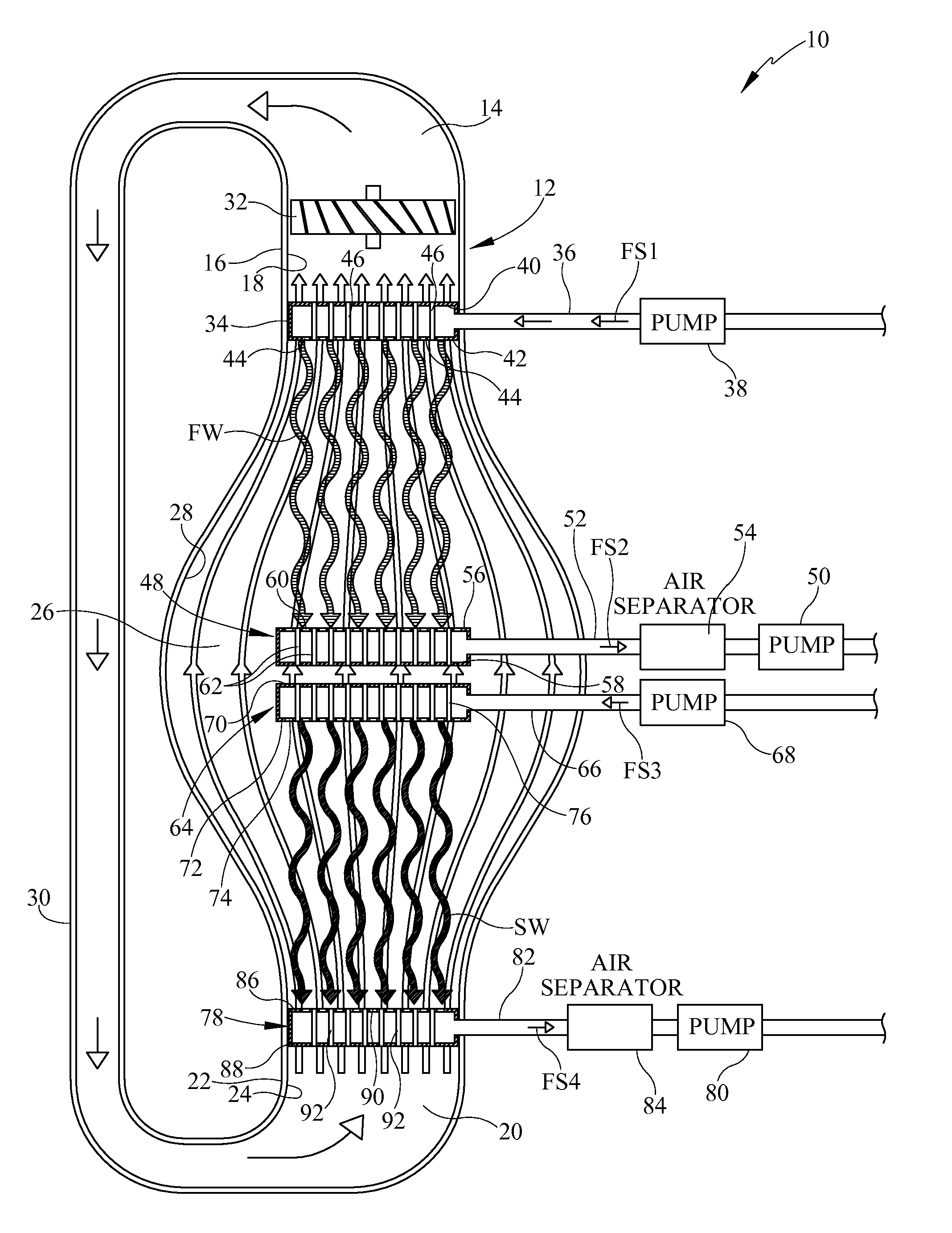
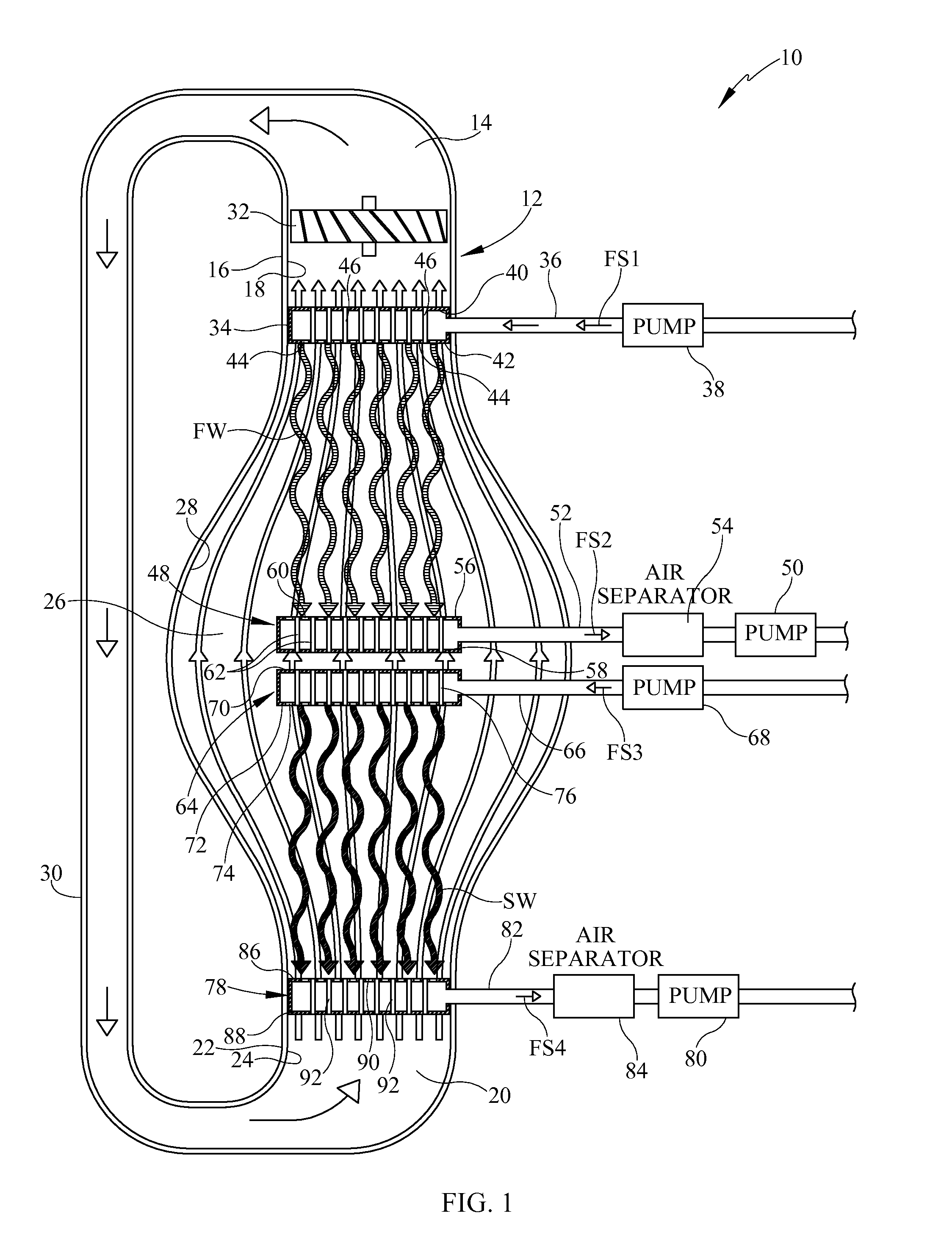
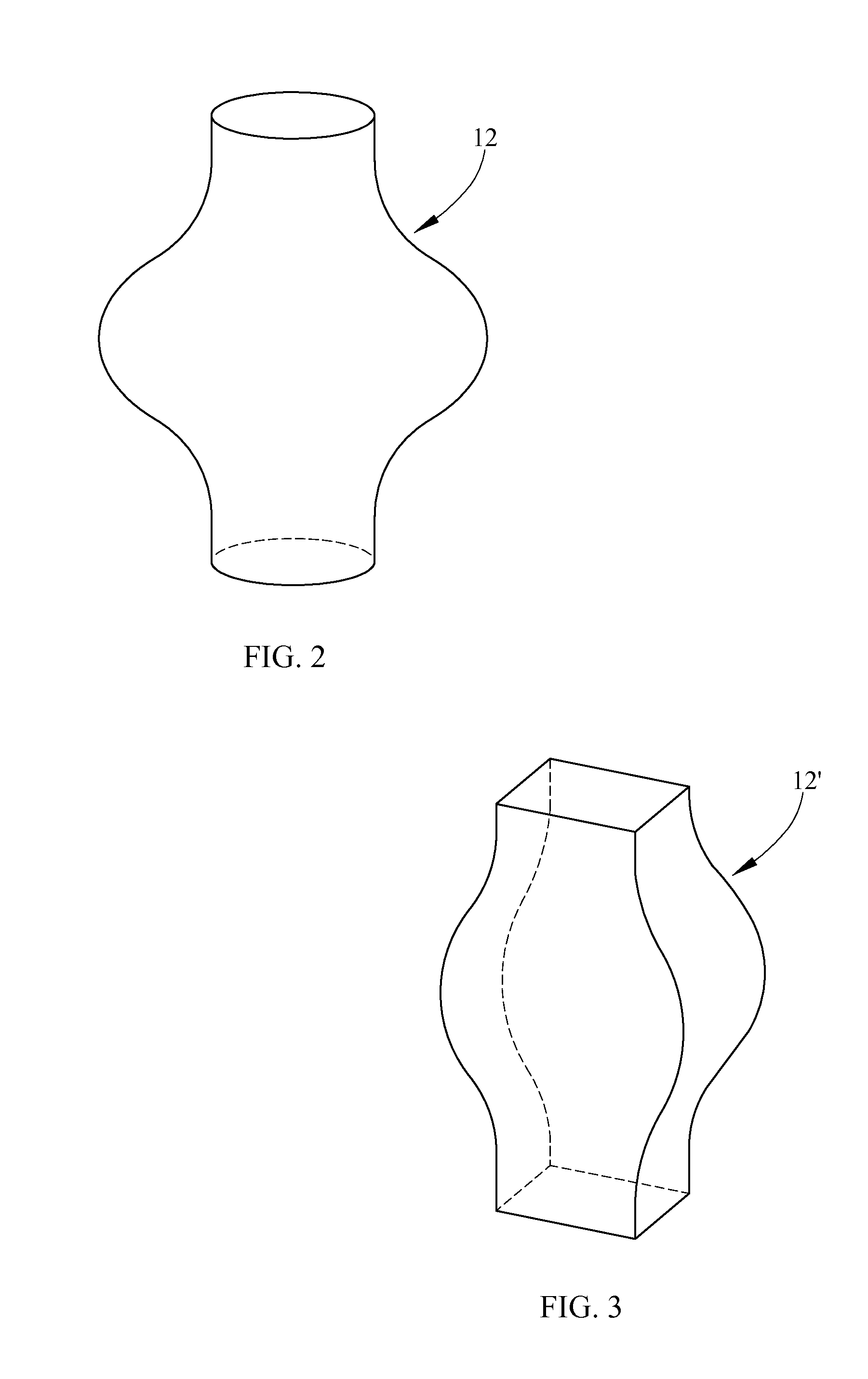
[0025]Referring now to the drawings, it is seen that the contoured humidification-dehumidification desalination system of the present invention, generally denoted by reference numeral 10, is comprised of a tower 12 which is a combined evaporator and condenser vessel that has an open top 14 having an upper neck portion 16 depending downwardly therefrom, the upper neck portion 16 having an internal wall 18 that is essentially straight, an open bottom 20 having a lower neck portion 22 depending upwardly therefrom, the lower neck portion 22 having an internal wall 24 that is essentially straight, and a main interior chamber 26 such that the internal wall 28 of the interior chamber 26 is essentially onion shaped in order to balance the thermodynamics of the process completely by facilitating the needed air bypass for a humidification-dehumidification desalination process.

[0026]As seen, a duct 30 fluid flow connects the open top 14 of the tower 12 with the open bottom 20 of the tower 12 w...


PUM

PropertyMeasurementUnit
temperatureaaaaaaaaaa
thermal energyaaaaaaaaaa
boiling pointaaaaaaaaaa

Abstract

A humidification-dehumidification water desalination system uses a contoured interior chamber, essentially onion shaped, in order to balance the thermodynamics of the evaporation/condensation process completely by facilitating the needed fluid bypass with air and the contoured shape of the interior chamber so that the desalination can occur energy efficiently in a single stage humidification-dehumidification system. The contour of the internal wall of the interior chamber is loosely proportional to the differential of the percentage of water vapor that can be carried by air as a function of temperature, with the interior chamber being essentially symmetrical about a horizontal midplane through the interior chamber.

Description

[0001]This application claims the benefit of U.S. provisional patent application, No. 61 / 853,239, filed on Apr. 1, 2013, which provisional patent application is incorporated herein by reference in its entirety.BACKGROUND OF THE INVENTION[0002]1. Field of the Invention[0003]The present invention relates to a humidification-dehumidification water desalination system that uses a single stage contoured evaporator / condenser.[0004]2. Background of the Prior Art[0005]Today multi-stage flash (MSF) and reverse osmosis (RO) are the two most commonly used technologies for water desalination. MSF is a vapor process where feed water initially is heated to its boiling point. As the water temperature drops and boiling stops, due to evaporative cooling, this water is then made to boil repeatedly by moving it from chamber to chamber, each chamber being at a progressively stronger vacuum until the water returns to its approximate original temperature. The produced steam is condensed, producing freshw...

Claims


Application Information

Patent Timeline
Patent Type & Authority Applications(United States)
IPC IPC(8): B01D3/00C02F1/04
CPCC02F1/04B01D3/00B01D3/28C02F1/10Y02A20/124B01D1/0094B01D3/343B01D5/006
Inventor BARTON, SEAN ANDERSONWINTON, ROBIN PATRICK
Owner MOLECULE SORTING SERVICES
Why Eureka
Try Eureka