Eureka AIR delivers breakthrough ideas for toughest innovation challenges, trusted by R&D personnel around the world.

Direct current (DC) microgrid charge/discharge system for secondary batteries connected in series

Active Publication Date: 2014-10-02
LG CNS +1
View PDF7 Cites 16 Cited by
  • Summary
  • Abstract
  • Description
  • Claims
  • Application Information

AI Technical Summary

Benefits of technology

The invention provides a method to increase the efficiency of a DC / DC converter used in electric vehicles by connecting multiple large capacity lithium batteries in series. However, each battery has a low operating voltage and high current, which reduces power conversion efficiency when used individually or in parallel. The invention sets the voltage of the DC microgrid system to be double the maximum voltage of the battery group, which increases the conversion resolution and energy conversion efficiency during power control. This allows the system to stably operate and reduces the size and cost of the entire system. The invention also uses a constant current power supply as a power source for charging and a single power supply to stably operate regardless of the number of batteries being charged. This prevents power loss and allows for simultaneous charging and discharging in a predetermined system.

Problems solved by technology

However, there are several technical difficulties, due to low conversion efficiency for converting electric energy of a battery with a relatively low voltage to an alternating current (AC) of a nationwide grid with a relatively high voltage, and for recycling the electric energy.
A direct current (DC)-to-AC (DC / AC) converter used to regenerate power may have extremely low conversion efficiency, for example typically 40%, since a voltage of a single battery is considerably lower than a voltage of a commercial AC grid (for example, 220 V or 380 V).
However, because each of the secondary batteries includes a separate discharge resistor and a switching element to form a discharge route circuit, power consumption, and manufacturing costs may increase.

Method used


Image

  • Direct current (DC) microgrid  charge/discharge system for secondary  batteries connected in series
  • Direct current (DC) microgrid  charge/discharge system for secondary  batteries connected in series
  • Direct current (DC) microgrid  charge/discharge system for secondary  batteries connected in series

Examples


embodiments

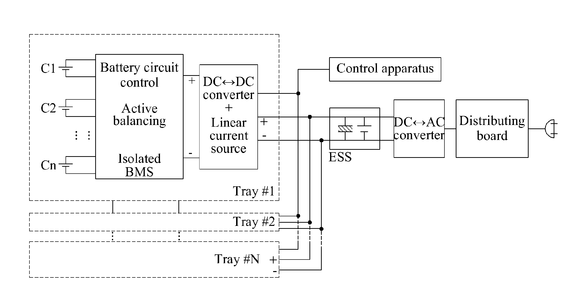
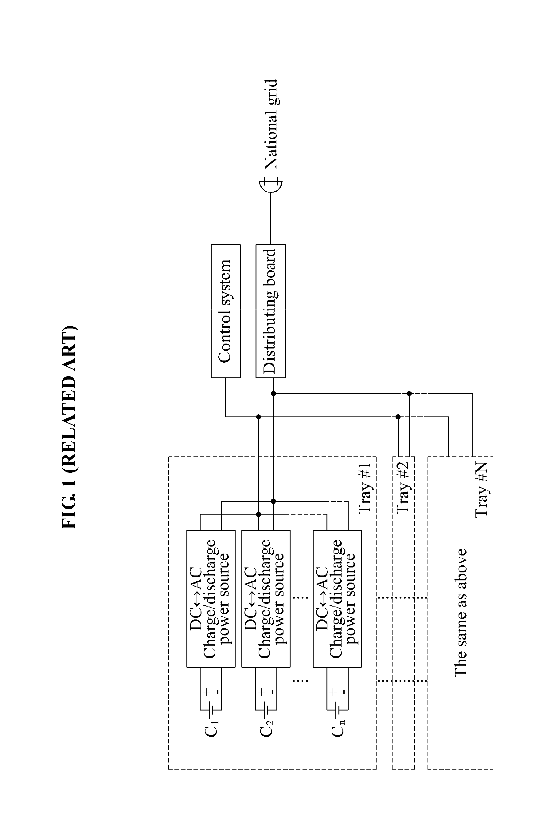
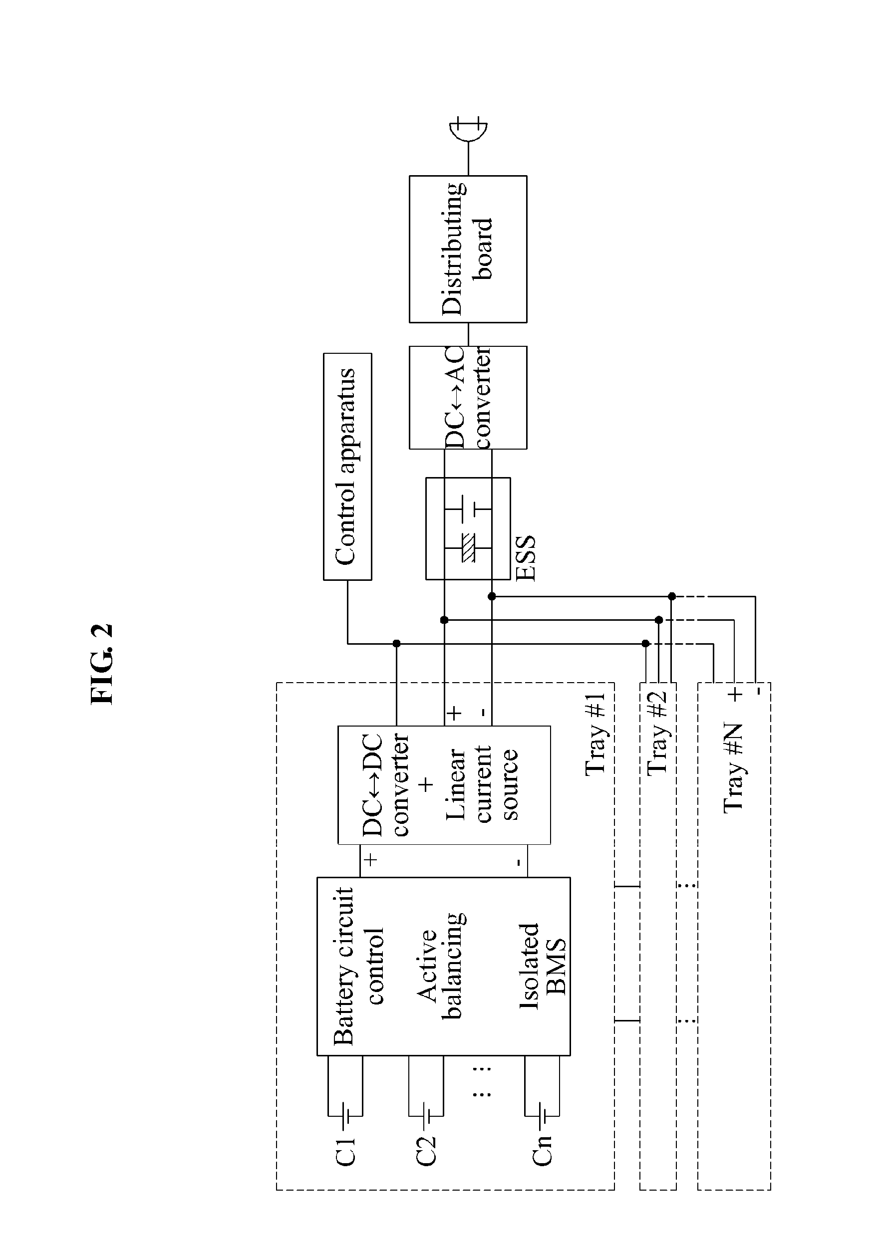
[0036]Embodiments of the present invention will be further described with reference to the drawings. FIG. 1 illustrates a charge / discharge system according to a related art. FIG. 2 illustrates a DC microgrid charge / discharge system according to an embodiment of the present invention.

[0037]The DC microgrid charge / discharge system of FIG. 2 may refer to a single charge / discharge power supply with a large capacity. The charge / discharge system of FIG. 1 may require the same number of bidirectional DC-AC charge / discharge power sources as the number of batteries.

[0038]Accordingly, compared to the charge / discharge system of FIG. 1, manufacturing costs of the DC microgrid charge / discharge system of FIG. 2 may be reduced, and the DC microgrid charge / discharge system of FIG. 2 may have a significantly low weight and an extremely small size, and may also occupy an extremely small space during installation.

[0039]In the present disclosure, the terms “charging and discharging” and “charge / dischar...


PUM


Abstract

An algorithm and a direct current (DC) microgrid charge / discharge system with the algorithm are provided that noticeably increases charge / discharge voltage during charging and discharging by connecting a plurality of secondary batteries in series, compared to a single battery, that increases power conversion efficiency of a DC-to-DC (DC / DC) converter for charge / discharge power control by setting an appropriate voltage of a DC microgrid to be about twice a maximum voltage of a battery group, that enables charging and discharging to be stably performed regardless of a change in the battery group by adding a linear constant current source, that increases power conversion efficiency of the DC microgrid charge / discharge system by configuring a DC energy storage system (ESS) used for both charging and discharging with a combination of a typical electrolytic condenser and a super condenser or a group of the secondary batteries, and that simplifies the DC microgrid charge / discharge system.

Description

CROSS-REFERENCE TO RELATED APPLICATION[0001]Pursuant to 35 U.S.C. §119(a), this application claims the benefit of earlier filing date and right of priority to Korean Patent Application No. 10-2013-0032882, filed on Mar. 27, 2013, the contents of which are hereby incorporated by reference herein in its entirety.BACKGROUND[0002]1. Field of the Invention[0003]The present invention relates to an algorithm and a direct current (DC) microgrid charge / discharge system with the algorithm that noticeably increases charge / discharge voltage during charging and discharging by connecting a plurality of secondary batteries in series, compared to a single battery, that increases power conversion efficiency of a DC-to-DC (DC / DC) converter for charge / discharge power control by setting an appropriate voltage of a DC microgrid that directly uses discharged electricity in a DC state to perform charging to be about twice a maximum voltage of a battery group, that increases power conversion efficiency of ...

Claims


Application Information

Patent Timeline
IPC IPC(8): H02J7/00H02J7/02
CPCH02J7/00H02J7/0014H02J7/1423H02J7/345Y02T10/92B60L53/20B60L58/19B60L58/22Y02T10/70Y02T10/7072Y02T90/14Y02T90/12Y02P80/14
Inventor KIM, JEONG MOOGLEE, HWAN HEERYU, TAE HYOUNGSHIN, DONG HOONHAN, CHEOL KYU
Owner LG CNS
Why Eureka
Eureka Blog
Learn More