Method and system using magnetic resonance imaging for tissue classification and bulk-density assignment

a magnetic resonance imaging and tissue classification technology, applied in the field of magnetic resonance imaging, can solve the problems of increasing the speed at which radiation therapy planning can be performed, and achieve the effect of reliably assigning accurate electron densities and reliably identifying additional tissue types

Inactive Publication Date: 2014-10-02
KONINKLJIJKE PHILIPS NV
View PDF1 Cites 22 Cited by
  • Summary
  • Abstract
  • Description
  • Claims
  • Application Information

AI Technical Summary

Benefits of technology

[0003]Magnetic Resonance (MR) images that can separate tissue, bone, and air are beneficial for all applications where MR is used in combination with irradiating imaging techniques, such as Positron Emission Tomography (PET) and Single Photon Emission Computed Tomography (SPECT), and with planning for irradiating therapy techniques, such as Magnetic Resonance—Radio Therapy simulation. Unlike Hounsfield units used in CT, there is no simple relation between the MR image intensity and tissue density. For instance, using conventional MR sequences, cortical bone and air filled cavities both show no signal intensity whereas their densities are substantially different. Ultimately the ability to reliably identify additional tissue types in an MR image while the MR-acquisition time should be kept at a minimum would be beneficial. Additionally, the ability to reliably assign accurate electron densities to different voxels of an MR image would be beneficial for allowing creation of a treatment dose plan based only on MR imaging, without the need for registering MR images with separately generated CT images of an imaging volume.

Problems solved by technology

This may result in an increase in the speed in which radiation therapy planning can be performed.

Method used


Image

  • Method and system using magnetic resonance imaging for tissue classification and bulk-density assignment
  • Method and system using magnetic resonance imaging for tissue classification and bulk-density assignment
  • Method and system using magnetic resonance imaging for tissue classification and bulk-density assignment

Examples


Embodiment Construction

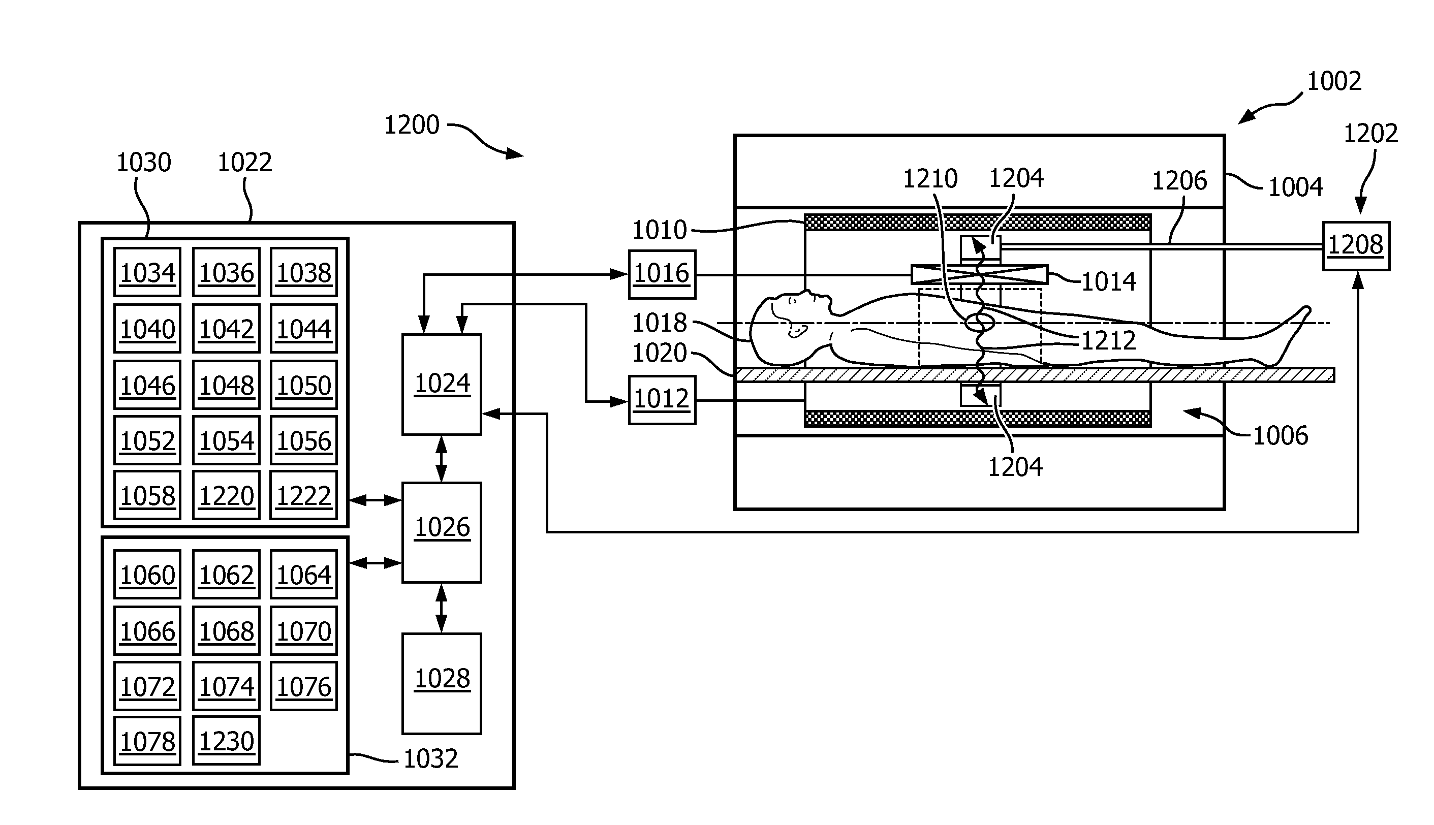
[0088]The present invention will now be described more fully hereinafter with reference to the accompanying drawings, in which embodiments of the present invention are shown. The present invention may, however, be embodied in different forms and should not be construed as limited to the embodiments set forth herein. Rather, these embodiments are provided as teaching examples of the invention. Within the present disclosure and claims, when something is said to have approximately a certain value, then it means that it is within 10% of that value, and when something is said to have about a certain value, then it means that it is within 25% of that value.

[0089]Like numbered elements in these figures are either equivalent elements or perform the same function. Elements which have been discussed previously will not necessarily be discussed in later figures if the function is equivalent.

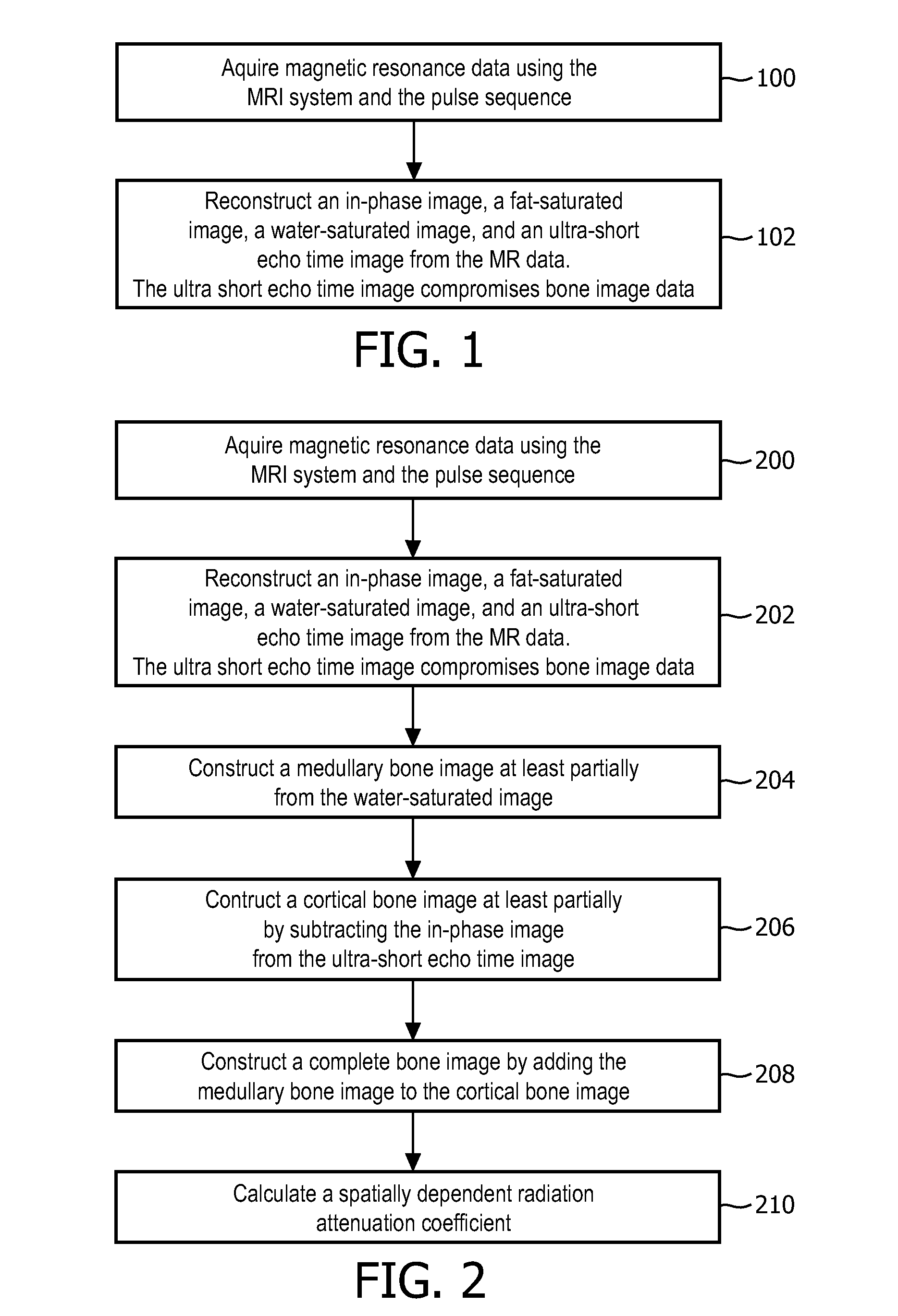
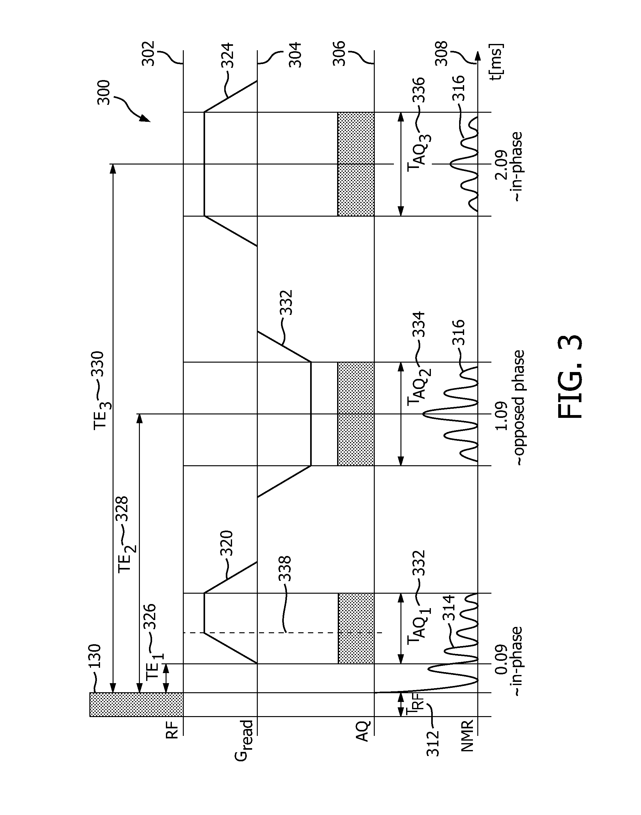
[0090]FIG. 1 shows a flow diagram which illustrates a method of acquiring and processing magnetic resona...


PUM


Abstract

An apparatus includes a magnetic resonance imaging system, a processor for controlling the apparatus, and a memory containing machine executable instructions and a pulse sequence. The machine executable instructions and pulse sequence cause the processor to control the apparatus to: acquire magnetic resonance data from an imaging volume, wherein the magnetic resonance data includes gradient echo data; segment the magnetic resonance data into a plurality of segments, the segments including a fat segment, a water segment, a cortical bone segment, and an air segment; and create a bulk density map of the imaging volume from the segments.

Description

CROSS-REFERENCES TO RELATED APPLICATIONS[0001]This is a continuation-in-part patent application under 35 U.S.C. §120 of U.S. patent application Ser. No. 14 / 126,979, filed on 17 Dec. 2013, which is a U.S. national stage application under 35 U.S.C. §371 of International Application PCT / IB2012 / 053,050, filed on 18 Jun. 2012, which claims priority from European patent application 11171444.0, filed on 27 Jun. 2011, and U.S. Provisional Patent Application Ser. No. 61 / 636,102, filed on 20 Apr. 2012. Priority to all of these patent applications is claimed, and all of these patent applications are all hereby incorporated by reference in their entirety as if fully set forth herein.TECHNICAL FIELD[0002]The invention relates to magnetic resonance imaging, in particular to the use of magnetic resonance imaging for radiation therapy planningBACKGROUND AND SUMMARY[0003]Magnetic Resonance (MR) images that can separate tissue, bone, and air are beneficial for all applications where MR is used in com...

Claims


Application Information

Patent Timeline
Patent Type & Authority Applications(United States)
IPC IPC(8): G01R33/48G01R33/56
CPCG01R33/4808G01R33/5608G01R33/4828G01R33/481A61N2005/1062A61B8/5261A61N2005/1052A61B6/4417A61B6/00G01R33/4816A61B8/0875A61N5/1039A61B6/037A61B6/04G01R33/5616A61N2005/1055
Inventor REMMELE, STEFANIEBOERNERT, PETERKOTYS, MELANIE SUZANNE
Owner KONINKLJIJKE PHILIPS NV
Why Eureka
Try Eureka