Fluid ejection device and medical apparatus

Inactive Publication Date: 2014-10-02
SEIKO EPSON CORP
View PDF4 Cites 13 Cited by
  • Summary
  • Abstract
  • Description
  • Claims
  • Application Information

AI Technical Summary

Benefits of technology

[0008]An advantage of some aspects of the invention is to solve at least a part of the problems described above, and the invention can be implemented as the following aspects.

Problems solved by technology

That is, this device may or may not have an ejection pipe.

Method used


Image

  • Fluid ejection device and medical apparatus
  • Fluid ejection device and medical apparatus
  • Fluid ejection device and medical apparatus

Examples


first embodiment

A. First Embodiment

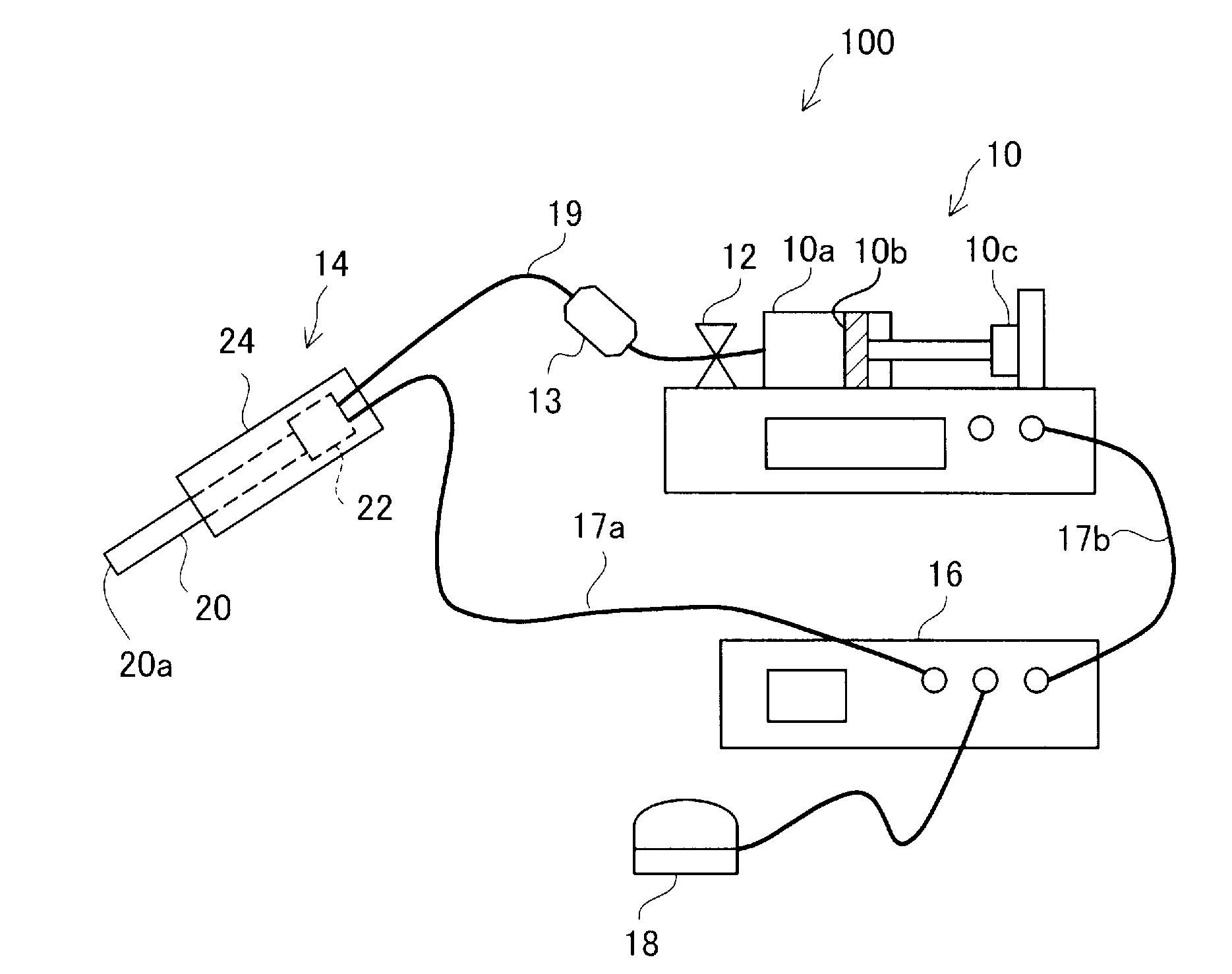
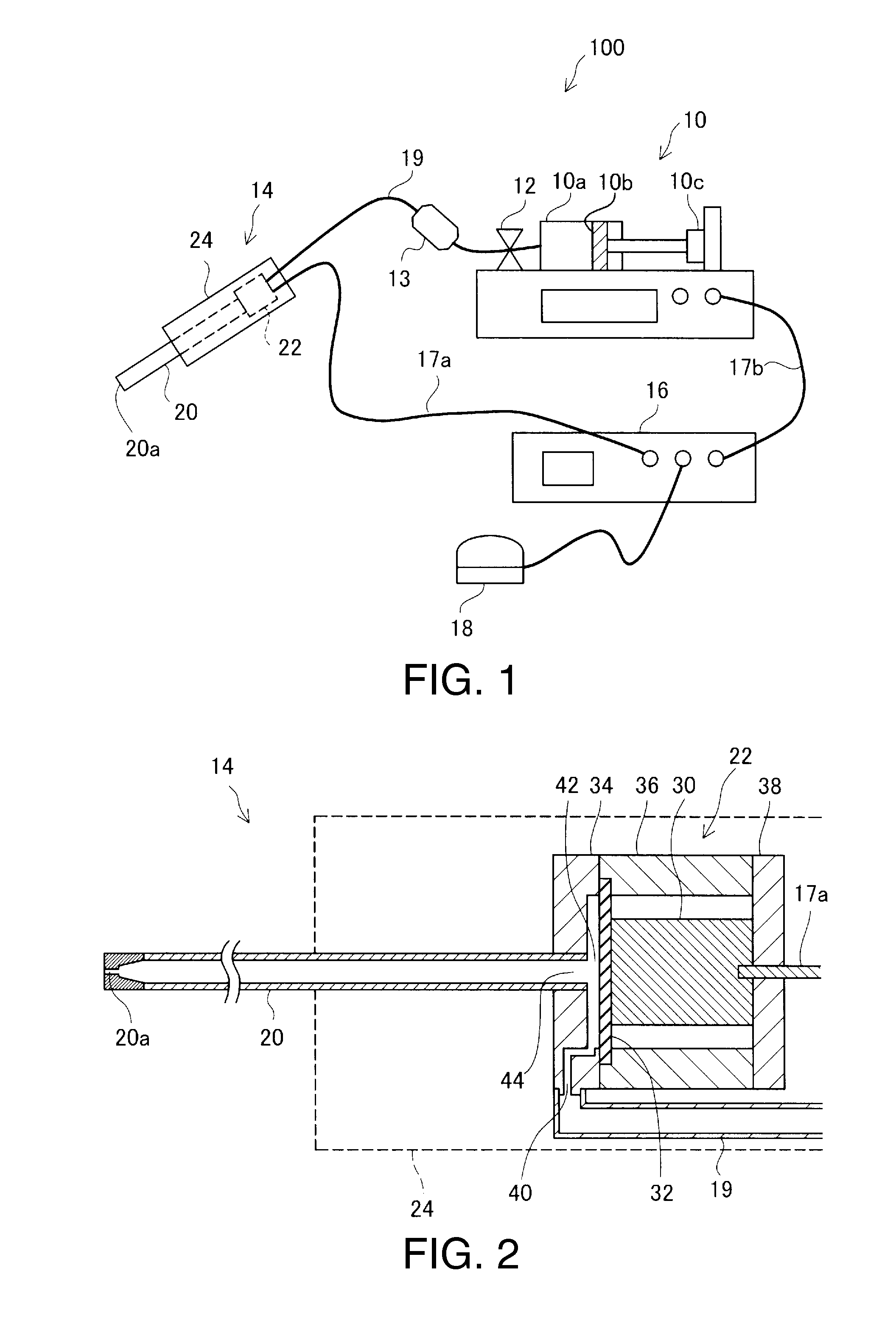
[0029]FIG. 1 is an explanatory view showing the configuration of a fluid ejection device 100 as an embodiment of the invention. The fluid ejection device 100 of this embodiment is a medical apparatus used in a medical institution and has the function of a surgical knife which ejects a fluid to an affected part and thereby incises or excises the affect part.

[0030]The fluid ejection device 100 has a fluid supplying unit 10, a handpiece 14, a controller 16, and a foot switch 18. The fluid supplying unit 10 and the handpiece 14 are connected to each other by a connection tube 19 made of a resin.

[0031]The connection tube 19 is provided with a valve 12 as an opening / closing unit to open and close the channel, and a filter 13 to eliminate foreign matters, bacteria, air bubbles and the like from inside the connection tube 19.

[0032]The fluid supplying unit 10 supplies a fluid to the handpiece 14 via the connection tube 19. In this embodiment, the fluid supplying unit 10 is...

second embodiment

B. Second Embodiment

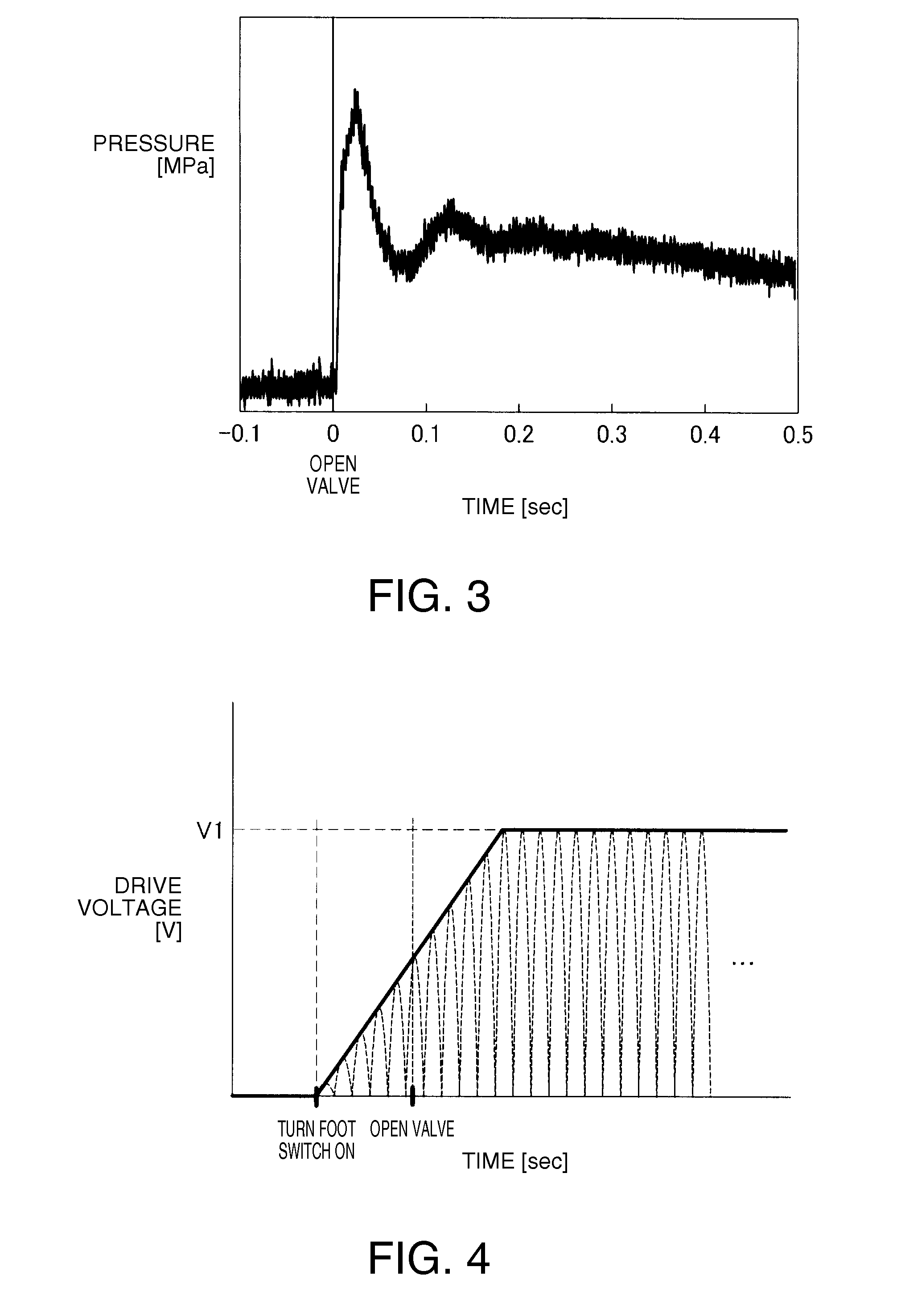
[0059]FIG. 6 is an explanatory view showing a change in the maximum voltage of the drive voltage applied to the piezoelectric element 30 in a second embodiment. FIG. 7 is an explanatory view showing an example of a timing chart in the case where the foot switch 18 is turned on in the second embodiment. The second embodiment is different from the first embodiment shown in FIGS. 4 and 5, only in that the drive voltage is applied to the piezoelectric element 30 after the valve 12 is opened. The other configurations are the same as in the first embodiment.

[0060]According to this embodiment, since the driving of the piezoelectric element 30 is started after the supply of the fluid to the fluid chamber 42 is started, driving of the piezoelectric element 30 in the state where the fluid chamber 42 is short of the fluid can be restrained. As a result, generation of air bubbles due to the driving of the piezoelectric element 30 in the state where the fluid chamber 42 is sh...

third embodiment

C. Third Embodiment

[0062]FIG. 8 is an explanatory view showing a change in the maximum voltage of the drive voltage applied to the piezoelectric element 30 in a third embodiment. FIG. 9 is an explanatory view showing an example of a timing chart in the case where the foot switch 18 is turned on in the third embodiment. The third embodiment is different from the first embodiment shown in FIGS. 4 and 5, only in that the drive voltage is applied to the piezoelectric element 30 after the lapse of a predetermined time after the valve 12 is opened and that the maximum voltage of the drive voltage is already the predetermined voltage V1 immediately after the start of the application. The other configurations are the same as in the first embodiment.

[0063]FIG. 10 is a flowchart showing processing in the case where the foot switch 18 is turned on in the third embodiment. The controller 16 determines whether the foot switch 18 is on or not (step S10). If the foot switch 18 is on, the controlle...


PUM


Abstract

A fluid ejection device which ejects a fluid includes: an ejection pipe having an opening to eject the fluid; a fluid chamber which communicates with the ejection pipe and changes in volume due to displacement of a piezoelectric element; a supply channel which communicates with the fluid chamber; an opening/closing unit which is provided on the supply channel and opens and closes the supply channel; a fluid supplying unit which pressurizes the fluid and supplies the fluid to the fluid chamber via the supply channel; and a voltage controller which applies a drive voltage to the piezoelectric element. The voltage controller controls the drive voltage applied to the piezoelectric element so that the drive voltage reaches a predetermined voltage after the supply channel is opened by the opening/closing unit.

Description

[0001]This application claims the benefit of Japanese Patent Application No. 2013-67719, filed on Mar. 28, 2013. The content of the aforementioned application is incorporated herein by reference in its entirety.BACKGROUND[0002]1. Technical Field[0003]The present invention relates to a fluid ejection device and a medical apparatus.[0004]2. Related Art[0005]As a medical apparatus which ejects a fluid to an affected part for treatment, for example, a device disclosed in JP-A-2008-82202 is known. In the fluid ejection device disclosed in JP-A-2008-82202, a piezoelectric element is driven to increase or decrease the volume of a fluid chamber, thus causing a pulsed flow (pulse flow) to be ejected from an ejection pipe.[0006]Since a fluid ejection device is used, for example, as a surgical knife, the force (strength) of a pulsed flow needs to be stable. Particularly in order to improve the sense of use experienced by the operator, there is a demand that a pulsed flow with a proper strength...

Claims


Application Information

Patent Timeline
Patent Type & Authority Applications(United States)
IPC IPC(8): B05B5/16A61B17/3203
CPCB05B5/16A61B2560/02A61B2017/32032A61B17/3203F04B43/046A61B2017/00017F04B49/065F04B53/06F04B2203/0402
Inventor UCHIDA, KAZUAKIKARASAWA, JUNICHIMATSUZAKI, TAKAHIRO
Owner SEIKO EPSON CORP
Why Eureka
Try Eureka