In-vehicle communication system and in-vehicle relay apparatus

a technology of in-vehicle communication and relay apparatus, which is applied in the direction of vehicle components, instruments, electric/fluid circuits, etc., can solve the problems of inability to determine whether or not the data from the vehicle ecu is correct, adversely affecting the entire system, and inability to connect an improper in-vehicle devi

Active Publication Date: 2014-10-02
AUTONETWORKS TECH LTD +2
View PDF24 Cites 44 Cited by
  • Summary
  • Abstract
  • Description
  • Claims
  • Application Information

AI Technical Summary

Benefits of technology

[0024]According to another aspect of the present disclosure, the in-vehicle relay apparatus has stored therein relay destination determination information, and performs information relay processing. The information relay processing can be appropriately performed, since the in-vehicle relay apparatus is configured, if a new in-vehicle device is connected for example, to perform updating of the relay destination determination information by acquiring relay destination determination information from an external device. Furthermore, since it is configured such that an update is only performed if the relay destination determination information acquired from the external device is information satisfying a predetermined condition, the update of the relay destination determination information can be made difficult, thus making it possible to prevent connection of an improper in-vehicle device from adversely affecting the entire system.

Problems solved by technology

The in-vehicle gateway apparatus disclosed in JP 2012-9941A updates data stored in the storage area with data from the vehicle ECUs, but cannot determine whether or not the data from the vehicle ECUs is correct.
For example, in a case where a new vehicle ECU is added to an in-vehicle network, data from the added vehicle ECU is not always correct.
If the added vehicle ECU is defective, malicious, or the like, updating of the data in the storage area with the data from this vehicle ECU may adversely affect the entire system.

Method used


Image

  • In-vehicle communication system and in-vehicle relay apparatus
  • In-vehicle communication system and in-vehicle relay apparatus
  • In-vehicle communication system and in-vehicle relay apparatus

Examples


embodiment 1

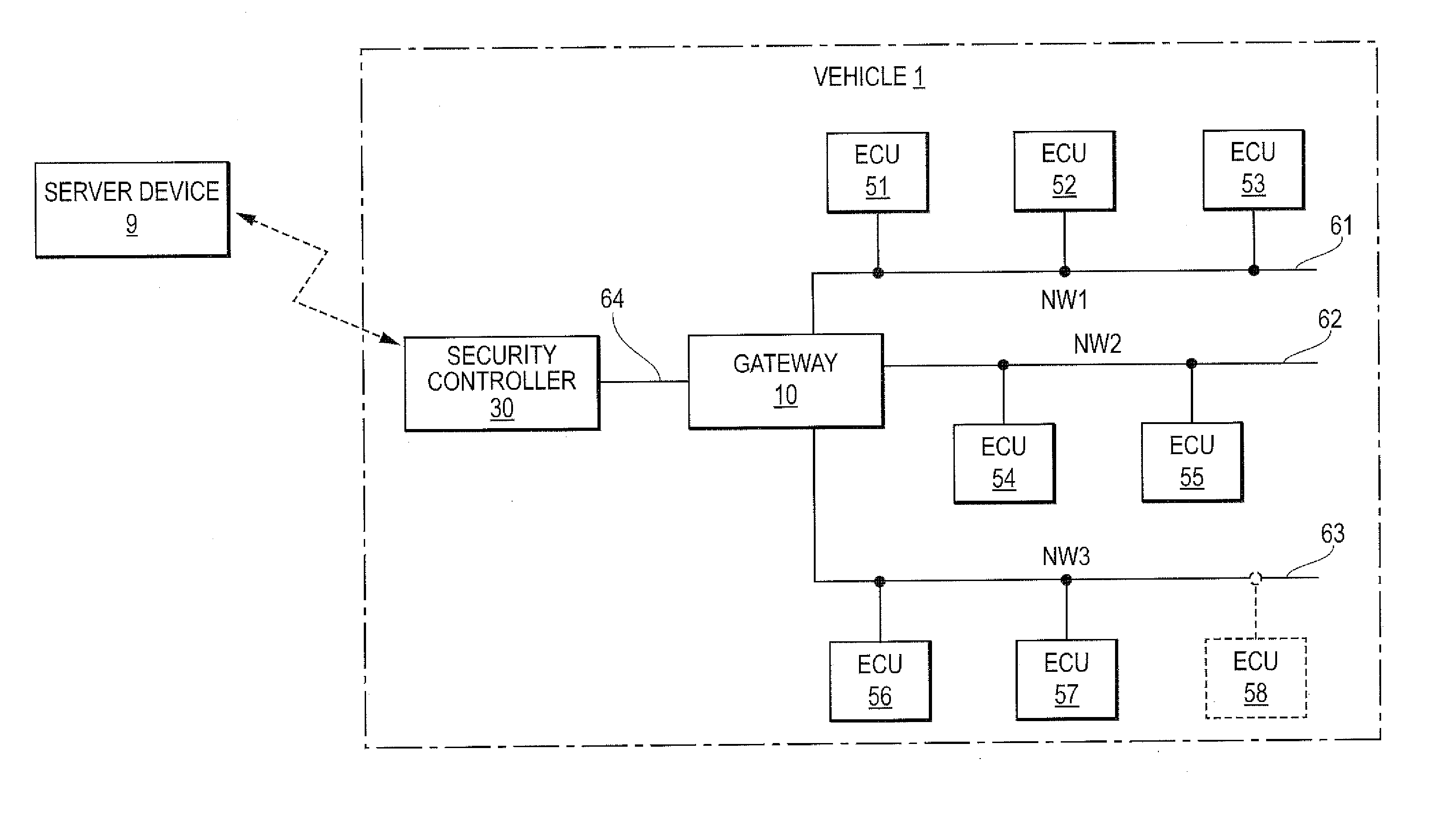
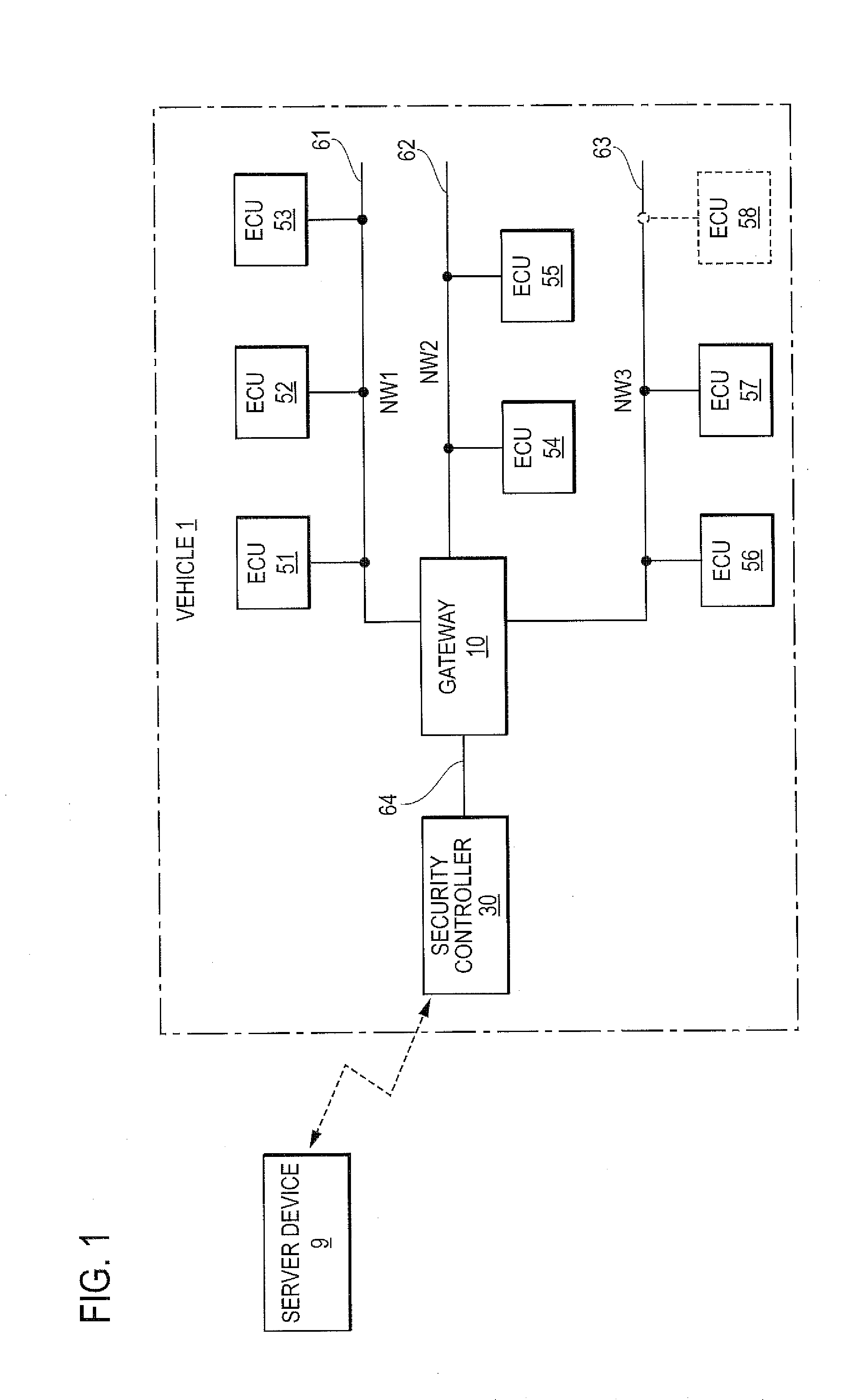
[0033]Hereinafter, various embodiments will specifically be described with reference to the drawings. FIG. 1 is a schematic diagram illustrating a configuration of an in-vehicle communication system according to the present embodiment. In the drawing, the reference numeral 1 indicated by the alternate long and short dash line denotes a vehicle, and the vehicle 1 includes a plurality of in-vehicle devices. Although in the present embodiment, the in-vehicle devices are referred to as ECUs 51, 52 etc., the in-vehicle devices may also include devices other than the ECUs. These ECUs 51, 52 etc. are connected to communication lines provided in the vehicle 1, and by the ECUs 51, 52 etc. communicating with one another to exchange information, various types of processing, such as cruise control of the vehicle 1, are realized.

[0034]In the present embodiment, the in-vehicle networks of the vehicle 1 are divided into three in-vehicle networks. In-vehicle network NW1 refers to a network in which...

modified example

[0066]The above-described in-vehicle communication system according to Embodiment 1 has the configuration in which the gateway 10 and the security controller 30 are provided as separate devices in the vehicle 1. In contrast, an in-vehicle communication system according to a modified example has a configuration in which a gateway 110 has the function of the security controller 30 as well (in other words, the security controller 30 has the function of the gateway 10 as well). FIG. 7 is a block diagram illustrating a configuration of the gateway 110 according to the modified example. The gateway 110 according to the modified example includes the wireless communication unit 34 that performs wireless communication with the server device 9.

[0067]Also, in the gateway 110 according to the modified example, the storage unit 12 includes the program storage unit 36a in which a program such as the update processing program 31a is stored. Furthermore, the authentication information 36b with whic...

embodiment 2

[0068]FIG. 8 is a schematic diagram illustrating a configuration of an in-vehicle communication system according to Embodiment 2. Note that, in FIG. 8, a detailed configuration of one ECU 250 is shown, and detailed configurations of other ECUs 250 are omitted since they may have the same configuration. Each ECU 250 according to Embodiment 2 includes a processing unit 251, a storage unit 252, a vehicle internal communication unit 253, and the like. The processing unit 251 is constituted by an arithmetic processing unit such as a CPU or an MPU, and performs various types of processing such as control processing on the vehicle 1. The storage unit 252 is constituted by a data rewritable non-volatile memory element, such as an EEPROM or a flash memory. The storage unit 252 has stored therein a reception permission list 252a, which is a list of IDs given to information that are permitted to be received by this ECU 250. The vehicle internal communication unit 253 is connected to a communic...


PUM


Abstract

An in-vehicle communication system and an in-vehicle relay apparatus that can perform relaying between multiple in-vehicle networks if a new in-vehicle device is connected to a said in-vehicle network, and that can prevent, if an improper in-vehicle device is connected to the in-vehicle network, the entire system from being adversely affected by the improper in-vehicle device. The in-vehicle relay apparatus that relays information between the multiple in-vehicle networks has stored therein relay destination determination information necessary to determine a relay destination of information. If a new in-vehicle device is connected to any one of the in-vehicle networks, an acquiring unit communicates with a communication device to obtain updated relay destination determination information, a determination unit determines if the updated relay destination determination information is legitimate, and an updating unit updates the relay destination determination information of the in-vehicle relay apparatus.

Description

BACKGROUND[0001]The present disclosure relates to an in-vehicle communication system in which a plurality of in-vehicle devices, which are installed in a vehicle, communicate with one another and to an in-vehicle relay apparatus for use in this system.[0002]Conventionally, due to an increase in the number of in-vehicle devices installed in a vehicle, in-vehicle networks for transmitting and receiving information between the in-vehicle devices are becoming larger. Accordingly, in-vehicle networks are divided into multiple in-vehicle networks, and an in-vehicle relay apparatus, such as a gateway, is used so as to relay transmission and reception of information between the multiple in-vehicle networks.[0003]For example, JP 2012-9941A discloses an in-vehicle gateway apparatus that connects a multimedia ECU (Electronic Control Unit) for controlling an in-vehicle multimedia device to a plurality of vehicle ECUs for controlling the vehicle. The in-vehicle gateway apparatus includes a stora...

Claims


Application Information

Patent Timeline
Patent Type & Authority Applications(United States)
IPC IPC(8): B60R16/023H04L69/40
CPCB60R16/023H04L63/12H04L67/125H04L69/40
Inventor SHIMOMURA, YOSHIKUNIOKADA, HIROSHI
Owner AUTONETWORKS TECH LTD
Why Eureka
Try Eureka