Venting system for a fuel tank

Inactive Publication Date: 2014-10-09
ROBERT BOSCH GMBH
View PDF8 Cites 27 Cited by
  • Summary
  • Abstract
  • Description
  • Claims
  • Application Information

AI Technical Summary

Benefits of technology

[0025]In one advantageous refinement of the venting system according to the invention, the sorption filter is connected in fluid-conducting fashion via the first line and the delivery device arranged therein to the intake pipe at a first infeed point upstream of a throttle device of the internal combustion engine and is also connected to the intake pipe via the second line and the tank venting valve arranged therein at a second infeed point positioned downstream of the throttle device. Such a refinement is used in particular in the case of naturally aspirated engines. The venting system then in turn has two infeed points by which the evaporated fuel desorbed from the sorption filter can be supplied to the internal combustion engine. The delivery device can in particular advantageously deliver in the direction of the intake pipe and, despite a prevailing intake pipe negative pressure in the case of throttle device being partially or fully closed, in the direction of the sorption filter. It is thus for example also possible for a tank leakage diagnosis, specifically a coarse leakage diagnosis, to be performed while the internal combustion engine is running, during the operation thereof with negative

Problems solved by technology

In the case of turbocharged engines, hybrid vehicles and engines which operate the engine with the greatest possible level of dethrottling in order to reduce fuel consumption, the

Method used


Image

  • Venting system for a fuel tank
  • Venting system for a fuel tank
  • Venting system for a fuel tank

Examples


Example

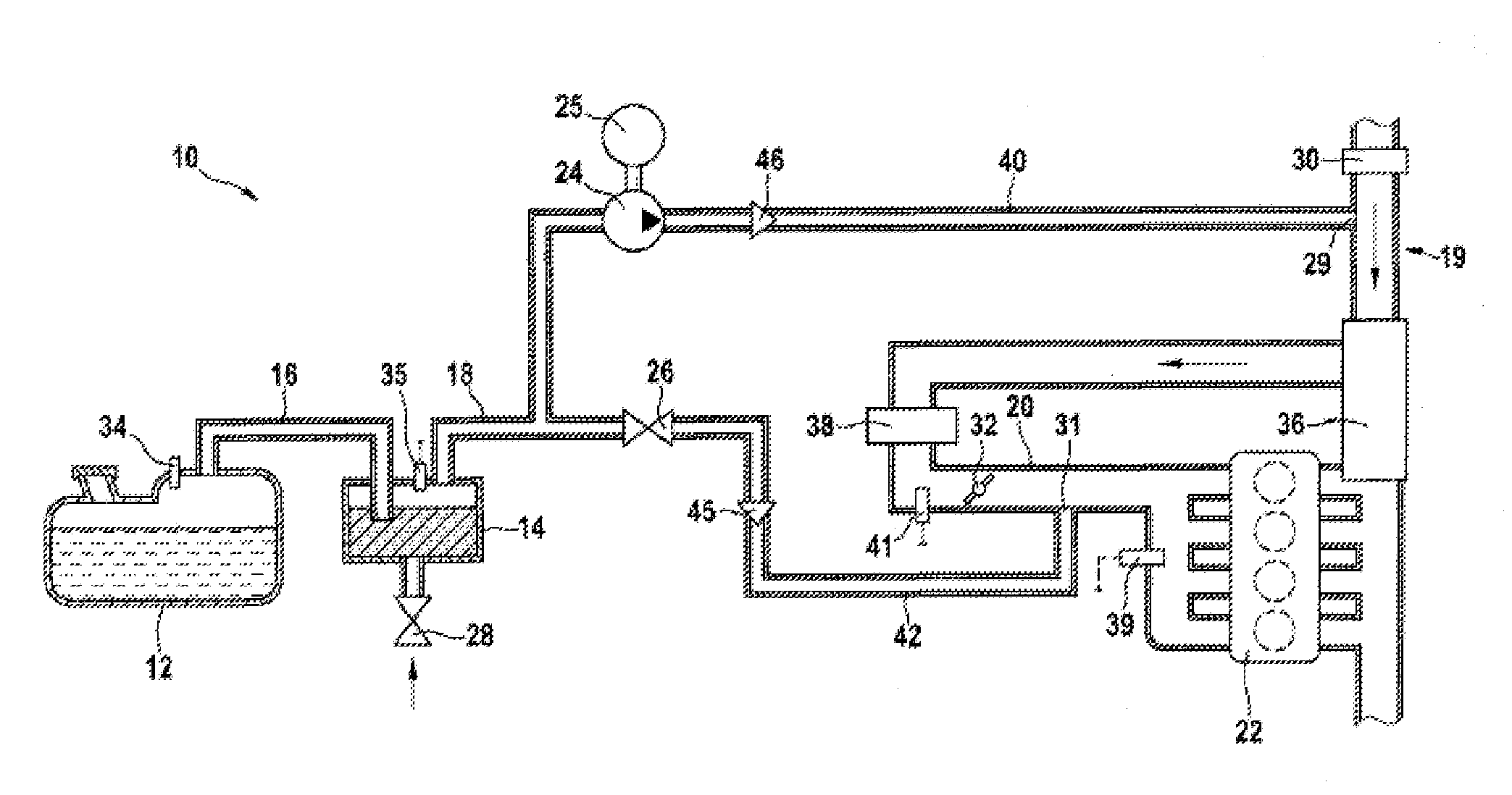
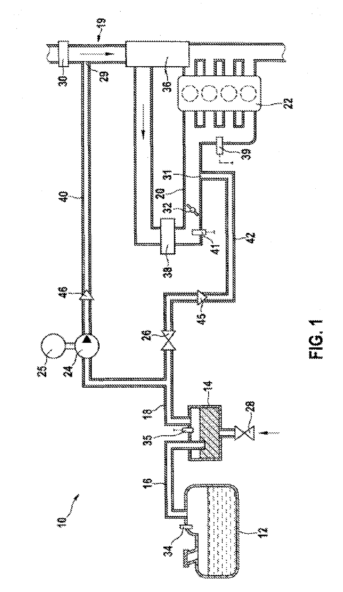
[0031]FIG. 1 illustrates a venting system 10 of an engine of a motor vehicle. The venting system 10 is coupled to a fuel tank 12 of the motor vehicle, wherein the coupling is established via a sorption filter 14 which serves for the temporary storage of fuel evaporating from the fuel tank 12.

[0032]The sorption filter 14 is connected to the fuel tank 12 via a tank connection line 16. Furthermore, the sorption filter 14 is connected in fluid-conducting fashion via a purging line 18 firstly via a first line to an air supply line 19 of the engine, in the present case of an internal combustion engine 22 in the form of a turbocharged engine, and secondly via a second line 42 to an intake pipe 20 of the engine.

[0033]In the air supply line 19 there are arranged an air mass sensor 30, a turbocharger unit 36 and a charge-air cooler 38. In the intake pipe 20 there is situated a throttle device 32, which in the present case is in the form of a throttle flap. The air supply line 19 is thus that ...


PUM


Abstract

A venting system for a fuel tank includes a sorption filter for temporarily storing fuel evaporating from the fuel tank and a delivery device arranged between the sorption filter and an air supply system of an internal combustion engine in a fluid-conducting manner. The internal combustion engine is a turbocharged engine with a turbocharger unit and a throttling device in the air supply system. The sorption filter is connected to the air supply system in a fluid-conducting manner by a first line at a first inlet point arranged upstream of the turbocharger unit and by a second line at a second inlet point arranged downstream of the throttling device. A tank venting valve is arranged in the second line, and the first line branches off from the second line upstream of the tank venting valve in the flow direction towards the second inlet point.

Description

PRIOR ART[0001]The invention relates to a venting system for a fuel tank, having a sorption filter for the temporary storage of fuel evaporating from the fuel tank and having a fluid line between the sorption filter and an air supply system of an internal combustion engine. The invention also relates to a venting system for a fuel tank, having a sorption filter for the temporary storage of fuel evaporating from the fuel tank and having a delivery device which is arranged in fluid-conducting fashion between the sorption filter and an air supply system of an internal combustion engine. Finally, the invention also relates to the use of a venting system of said type on a motor vehicle.[0002]In a fuel tank of a motor vehicle, depending on the pressure and temperature conditions prevailing in the fuel tank and a composition of the fuel, volatile substances evaporate, said volatile substances including mainly hydrocarbons and other volatile components in smaller fractions. For environmenta...

Claims


Application Information

Patent Timeline
IPC IPC(8): F02M25/08F02M35/10
CPCF02M35/10157F02M25/0836F02B29/0406F02B37/00F02D29/02F02D41/0007F02D41/0032F02D41/18F02D2200/0406F02M25/0818F02M35/1038F02M35/10386Y02T10/12
Inventor DENZ, HELMUT
Owner ROBERT BOSCH GMBH
Why Eureka
Try Eureka