Surface potential distribution measuring device and surface potential distribution measuring method

a technology of surface potential and measuring device, which is applied in the direction of dynamo-electric machine testing, electrostatic field measurement, instruments, etc., can solve the problems of inverter surge, high-voltage noise, and reflected wave,

Active Publication Date: 2014-10-09
TOSHIBA MITSUBISHI-ELECTRIC IND SYST CORP +1
View PDF11 Cites 8 Cited by
  • Summary
  • Abstract
  • Description
  • Claims
  • Application Information

AI Technical Summary

Benefits of technology

[0015]According to the present invention, the surface potential of the electric field reduction system in which the inverter pulse voltage is generated can be measured.

Problems solved by technology

On the other hand, in the inverter-driven system, a reflected wave may occur by impedance mismatching among the inverter, the cables, and the rotating electrical machine.
If the reflected wave is superimposed on the pulse voltage, high-voltage noise, so-called inverter surge may occur between the cables and the rotating electrical machine, especially, at a connecting portion between the cables and the rotating electrical machine.
When the pulse voltage including the inverter surge (hereinafter, referred to as “inverter pulse voltage”) repeatedly occurs, the partial discharge and heat generation at the stator coil of the core end portion (hereinafter, referred to as “stator coil end”) which are caused during operating time by commercial frequency become more serious.
As a result, the reliability of the stator coil may be significantly affected.

Method used


Image

  • Surface potential distribution measuring device and surface potential distribution measuring method
  • Surface potential distribution measuring device and surface potential distribution measuring method
  • Surface potential distribution measuring device and surface potential distribution measuring method

Examples


first embodiment

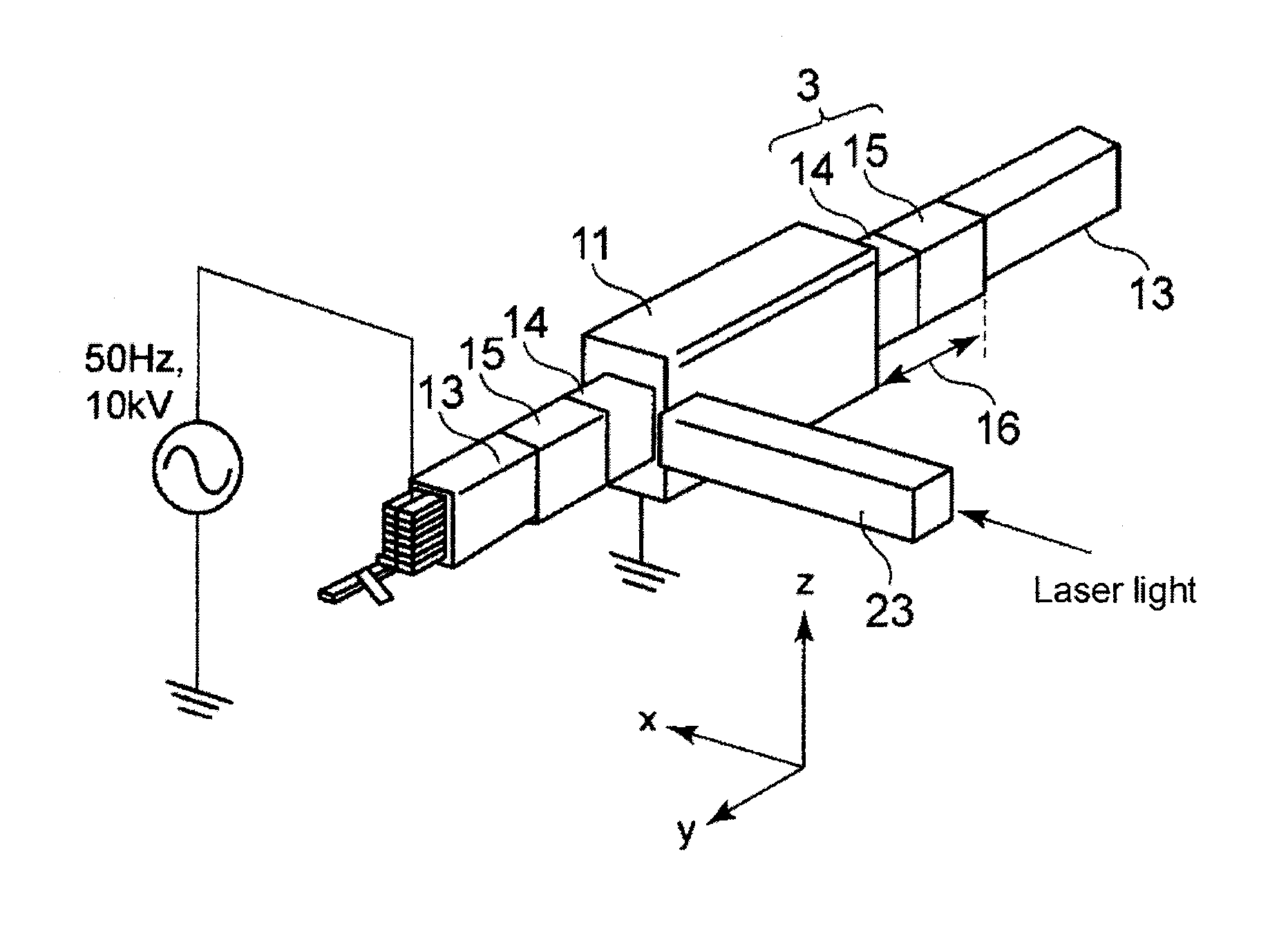
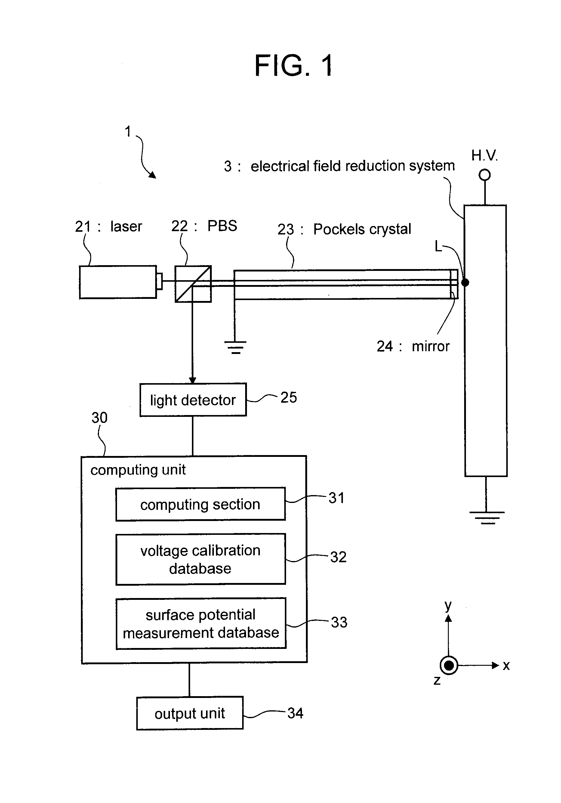
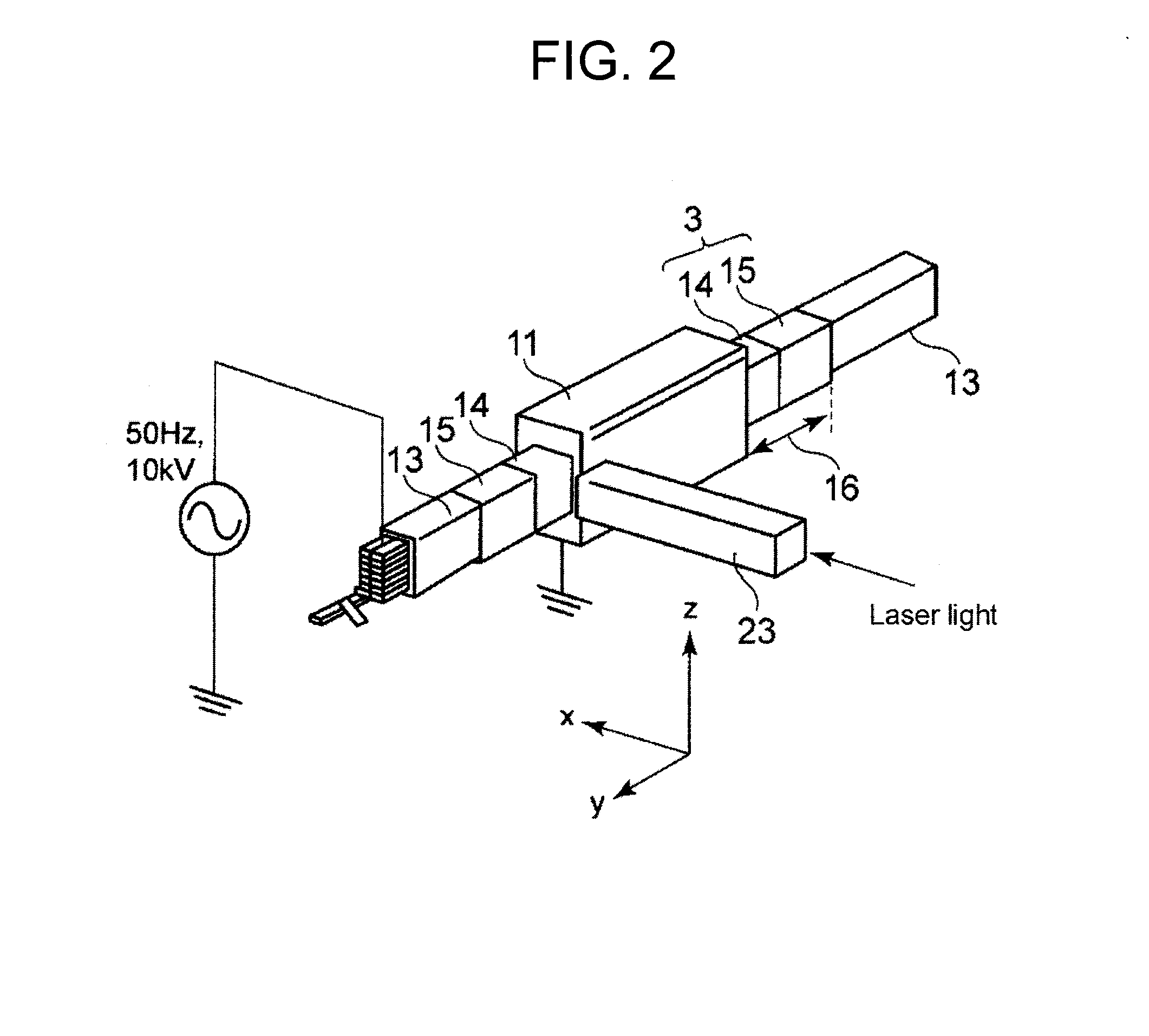
[0025]FIG. 1 is a block diagram illustrating a configuration of a surface potential distribution measuring device 1 according to a first embodiment. FIG. 2 is a perspective view schematically illustrating a stator of a rotating electrical machine, an electric field reduction system 3, and a Pockels crystal 23 of the surface potential distribution measuring device 1.

[0026]The surface potential distribution measuring device 1 is applied to the electric field reduction system 3 . The electric field reduction system 3 is applied to an inverter-driven rotating electrical machine.

[0027]The rotating electrical machine will be described using FIG. 2. In FIG. 2, constituent elements not directly related to the electric field reduction system 3 to be described later are omitted.

[0028]The rotating electrical machine includes a stator and a rotor . The rotor is disposed inside the stator and rotates therein.

[0029]The rotor includes a rotor shaft, a rotor core, and a rotor coil. The rotor core r...

second embodiment

[0087]A second embodiment will be described only for different portions thereof from the first embodiment. Other configurations not described are the same as those of the first embodiment.

[0088]Operation of the surface potential distribution measuring device 1 according to the second embodiment will be described.

[0089]The surface potential distribution measuring device 1 performs the voltage calibration processing before the test and then performs, during the test, the surface potential measurement processing and the potential difference computing processing to be described later. To the computing section 31, the voltage calibration processing is set, or a combination of the surface potential measurement processing and potential difference calculation processing is set by, e.g., the input operation of the operator.

[0090]FIG. 7 is a block diagram illustrating a configuration of the surface potential distribution measuring device 1 according to the second embodiment.

[0091]A plurality ...


PUM


Abstract

In a surface potential distribution measuring device for an electric field reduction system of a rotating electrical machine, a Pockels crystal is used between a laser and the surface (test location) of the electric field reduction system. Thus, the light Light intensity of a laser beam reflected on a mirror provided between the Pockels crystal and the test location corresponds to an output voltage that is the voltage difference between the first end surface and the second end surface of the Pockels crystal. Even when an inverter voltage is generated, by using a light detector having a frequency band capable of following the high frequency components of the inverter pulse voltage, the light intensity is detected by the light detector. Therefore, from the light intensity (output voltage), the surface potential distribution measuring device can measure the surface potential of the electric field reduction system in which an inverter pulse voltage is generated.

Description

TECHNICAL FIELD[0001]The present invention relates to a surface potential distribution measuring device and a surface potential distribution measuring method for an electric field reduction system of a rotating electrical machine.BACKGROUND ART[0002]An inverter-driven rotating electrical system that drives a rotating electrical machine using an inverter is now developed and widely used. In this inverter-driven system, the inverter transforms a DC voltage into a pulse voltage through switching operation and supplies the pulse voltage to the rotating electrical machine through cables. The rotating electrical machine is driven by a power of this pulse voltage.[0003]Conventionally, in a high-voltage rotating electrical machine, an electric field reduction system is often applied to a surface of a coil provided around a stator core end portion in order to prevent occurrence of a partial discharge or heat generation, especially, around a core end portion of a stator coil. In the electric ...

Claims


Application Information

Patent Timeline
Patent Type & Authority Applications(United States)
IPC IPC(8): G01R29/14
CPCG01R29/14G01R31/34G01R15/242G01R31/1227
Inventor TSUBOI, YUICHIYAMADA, SHINICHIROYOSHIMITSU, TETSUOHIDAKA, KUNIHIKOKUMADA, AKIKOIKEDA, HISATOSHI
Owner TOSHIBA MITSUBISHI-ELECTRIC IND SYST CORP
Why Eureka
Try Eureka