Dynamic Tomography Angle Selection

a tomography angle and dynamic technology, applied in the field of tomographic imaging, can solve the problems of limited data, computationally more intensive, and limited reconstruction, and achieve the effect of accurate tomographic imaging

Active Publication Date: 2014-10-16
UNIVERSITY OF ANTWERP +1
View PDF6 Cites 19 Cited by
  • Summary
  • Abstract
  • Description
  • Claims
  • Application Information

AI Technical Summary

Benefits of technology

[0010]It is an object of embodiments of the present invention to provide accurate tomographic imaging. It is an advantage of embodiments of the present invention that good methods and systems are provided for limited-data discrete tomographic imaging.

Problems solved by technology

Unfortunately, the iterative nature of these methods renders them computationally more intensive.
Such reconstruction problems are known as limited-data problems.
In electron tomography, for example, the electron beam may damage the sample, limiting the number of projections that can be acquired.
In industrial tomography for quality assurance, cost considerations impose limitations on the duration of a scan, and thereby on the number of projections.
Applying classical reconstruction algorithms such as Filtered Backprojection to limited-data problems often results in inferior reconstruction quality.

Method used


Image

  • Dynamic Tomography Angle Selection
  • Dynamic Tomography Angle Selection
  • Dynamic Tomography Angle Selection

Examples


Embodiment Construction

[0050]The present invention will be described with respect to particular embodiments and with reference to certain drawings but the invention is not limited thereto but only by the claims. The drawings described are only schematic and are non-limiting. In the drawings, the size of some of the elements may be exaggerated and not drawn on scale for illustrative purposes. The dimensions and the relative dimensions do not correspond to actual reductions to practice of the invention.

[0051]Furthermore, the terms first, second and the like in the description and in the claims, are used for distinguishing between similar elements and not necessarily for describing a sequence, either temporally, spatially, in ranking or in any other manner. It is to be understood that the terms so used are interchangeable under appropriate circumstances and that the embodiments of the invention described herein are capable of operation in other sequences than described or illustrated herein.

[0052]Moreover, t...


PUM


Abstract

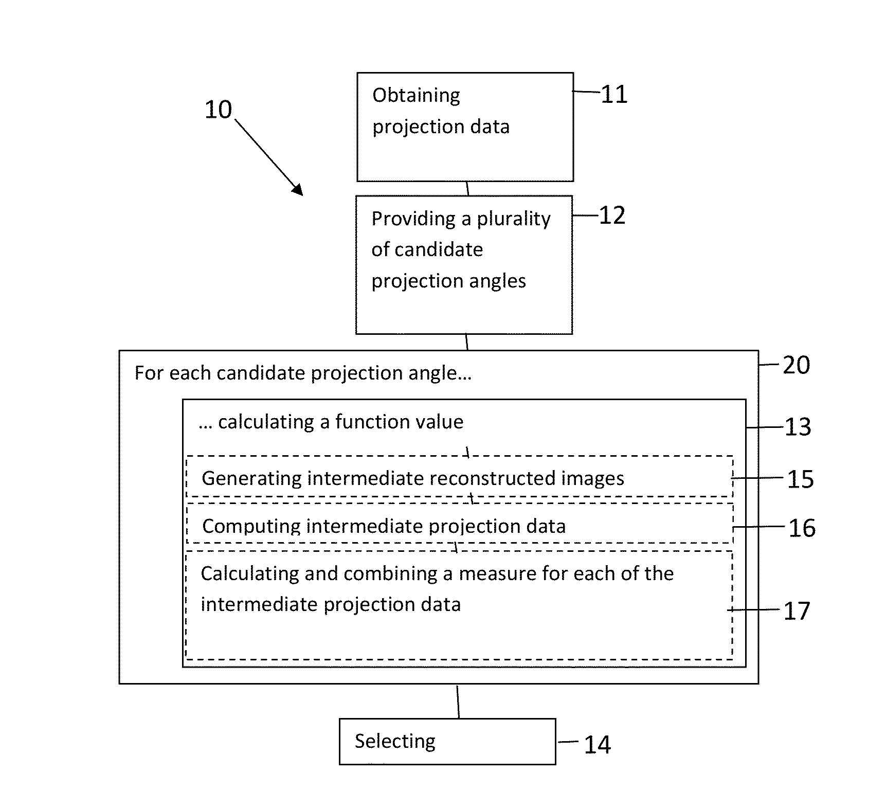
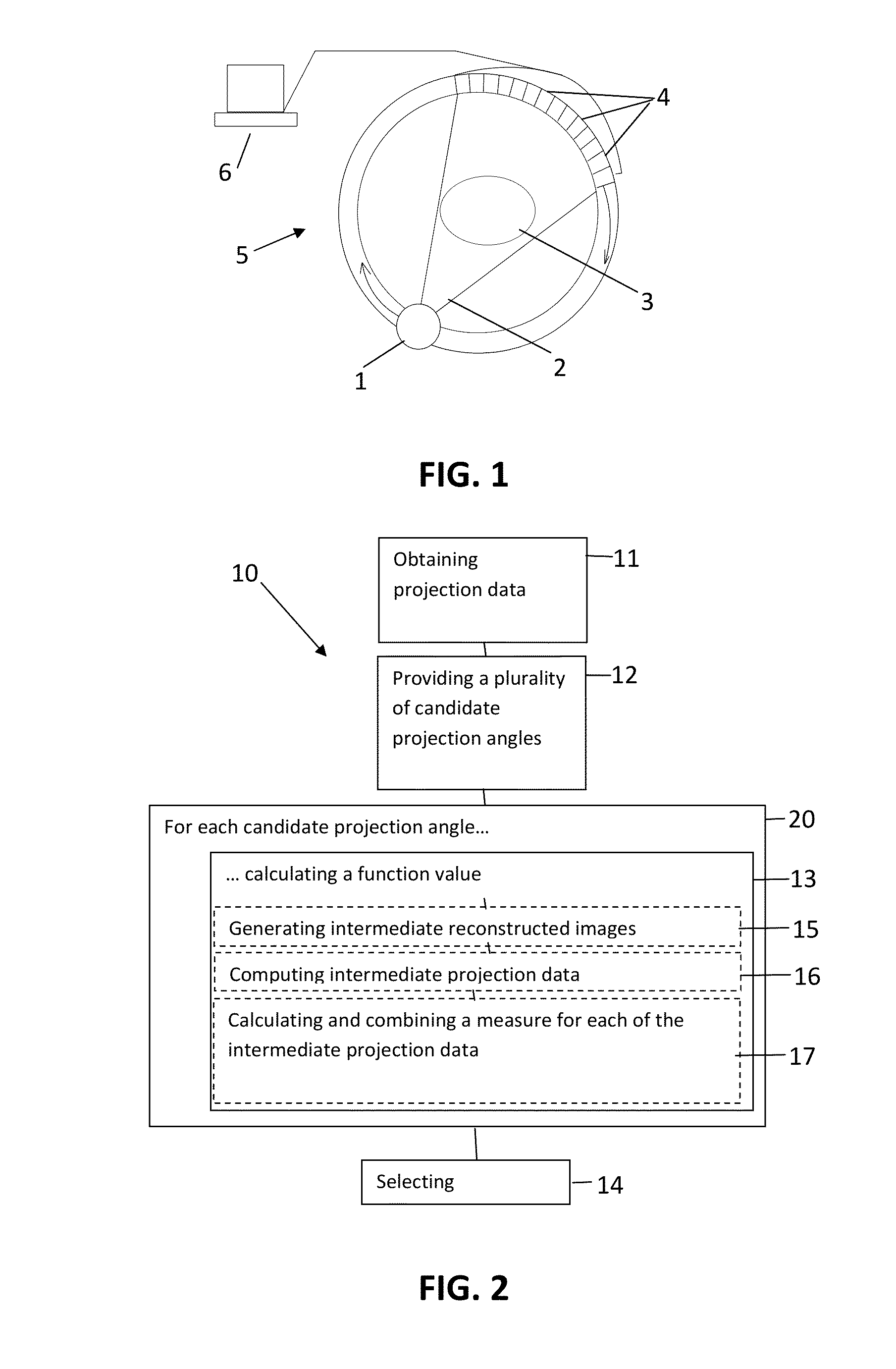
A method for determining a projection angle for use in tomographic imaging comprises obtaining projection data including at least one projection view from at least one projection angle. The at least one projection view is generated by scanning a test object with a tomographic imaging device. Each projection view comprises at least one observation value obtained at least one detection location, providing a plurality of candidate projection angles, for each candidate projection angle, calculating a function value indicative of an amount of information that may be gained by adding to the projection data a further projection view generated by scanning of the test object with the tomographic imaging device from the candidate projection angle, and selecting a candidate projection angle from the plurality of candidate projection angles taking into account the function values. A corresponding system and computer program product also is provided.

Description

FIELD OF THE INVENTION[0001]The invention relates to the field of tomographic imaging. More specifically it relates to methods and systems for optimization of a set of projections for tomographic reconstruction.BACKGROUND OF THE INVENTION[0002]In tomographic imaging, penetrating waves are used to gather projection data from an object under study from multiple directions, e.g. acquired along a range of angles. Images of the object may then be reconstructed from these projections. Different tomographic imaging modalities exist for different types of penetrating waves, for example, computed tomography generally refers to X-ray tomography, single-photon emission computed tomography and positron emission tomography refer to gamma ray tomography, magnetic resonance imaging uses radiofrequent waves, and other modalities exist for visible light, electron waves and ultrasound.[0003]In the case of computed tomography, internal structure of a patient or object may be examined non-invasively. T...

Claims


Application Information

Patent Timeline
Patent Type & Authority Applications(United States)
IPC IPC(8): G06T11/00
CPCG06T11/005A61B6/508G06T2211/436G06T2211/424A61B6/583
Inventor BATENBURG, KEES JOOSTSIJBERS, JAN
Owner UNIVERSITY OF ANTWERP
Why Eureka
Try Eureka