Solar energy system

a solar energy system and solar collector technology, applied in the field of solar energy, can solve the problems of limiting the transfer rate and distance, preventing effective heat transfer, and affecting the efficiency of solar collectors, etc., and achieves the effects of improving the return on investment (roi), high efficiency and low cos

Inactive Publication Date: 2014-10-23
ORG WORLD INTPROP
View PDF9 Cites 7 Cited by
  • Summary
  • Abstract
  • Description
  • Claims
  • Application Information

AI Technical Summary

Benefits of technology

[0014]The disclosed solar energy system enables use of solar radiation to produce heat, electricity and also distilled water at the same time. This significantly improves the return on investment (ROI) compared to the existing solar systems, to wit, photovoltaics or solar thermal. For many applications, purified water holds much higher value than that of electricity or heat produced by the solar system.
[0015]The disclosed solar energy system utilizes a three-horizontal pipe structure interconnecting vertically inclined pipes that form a piping matrix connected to the bottom of a solar collector to provide a highly efficient and inexpensive device for producing heat and distilled water.
[0016]Compared to non-phase-transition working fluid circulation (natural or forced), the disclosed system has much better performance in terms of heat throughput because heat transfer by phase transition can collect (and release) a much larger amount of heat. Compared to forced circulation, which consumes electricity, this system is operable without electricity for working fluid circulation.
[0017]As a water purifier or desalinator, it does not consume an expensive filter cartridge, such as a reverse osmosis (RO) filter. It also does not consume noticeable energy (or even solar energy), unlike traditional water distillation. Rather, distilled water is a byproduct of a phase-transitional thermal transport process.

Problems solved by technology

However for the heat pipe, there is one drawback of contra-flow of vapor and liquid in the same pipe, which limits the transfer rate and the distance.
However, this technology introduces problems associated with the liquid level inside of the solar collector: if the liquid level is low, there can be a deficit of liquid in the upper part of the solar collector and, as a consequence, the temperature of the solar collector can rise to destructive levels, especially for a combination photovoltaic and thermal application.
Also, when the liquid level is high, there can be a large flow of liquid out of the vapor pipe, preventing effective heat transfer.
Solar energy is still not quite competitive to traditional fossil energy in terms of return on investment (ROI).

Method used


Image

  • Solar energy system
  • Solar energy system
  • Solar energy system

Examples


Embodiment Construction

[0026]In the following description, reference is made to the accompanying drawings, which form a part hereof and which illustrate several embodiments of the present invention. The drawings and the preferred embodiments of the invention are presented with the understanding that the present invention is susceptible of embodiments in many different forms and, therefore, other embodiments may be utilized and structural, and operational changes may be made without departing from the scope of the present invention.

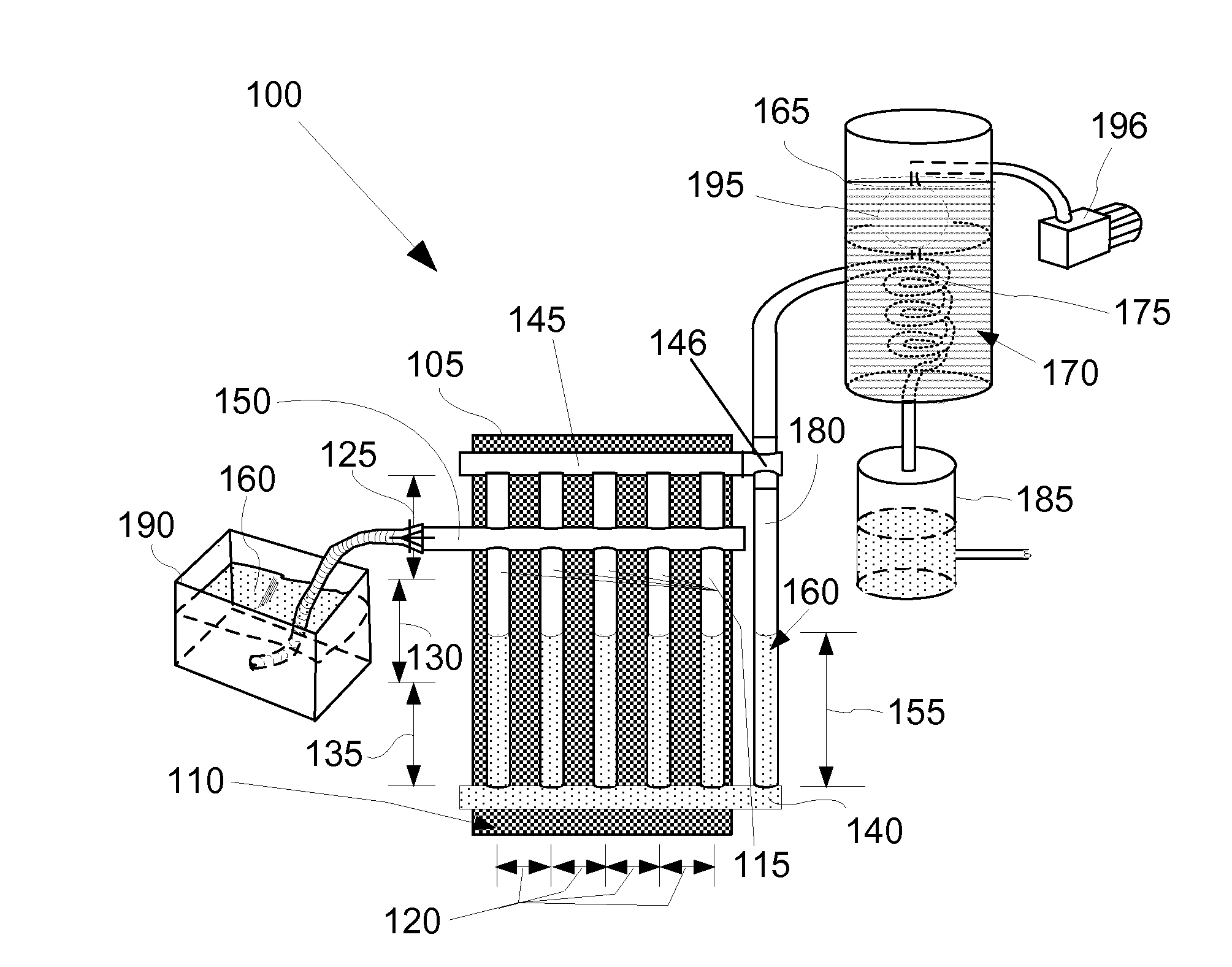
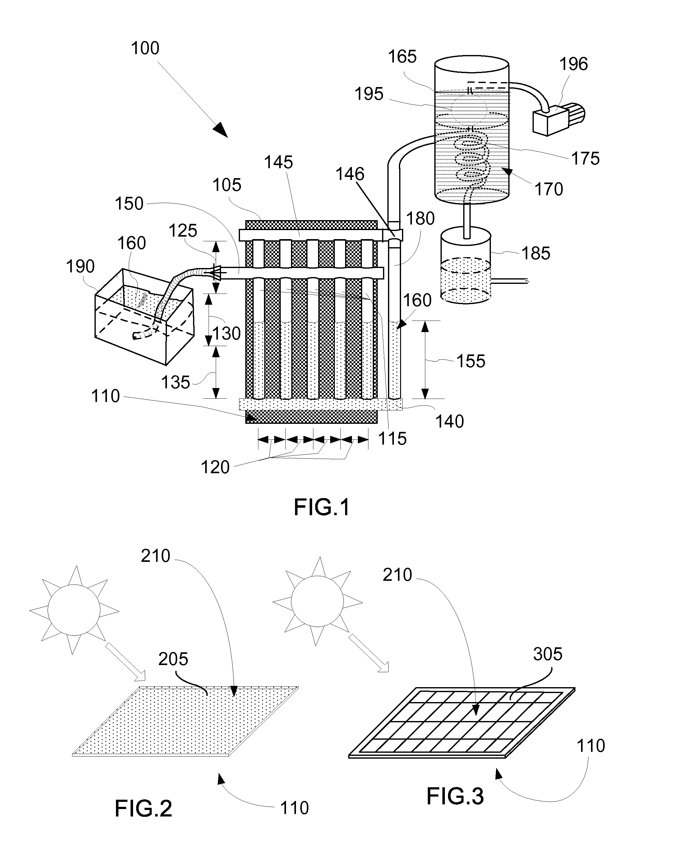
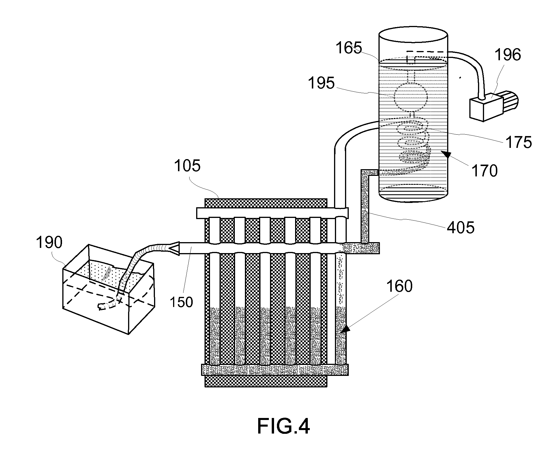
[0027]A solar energy system (100), shown in FIG. 1, includes: a solar energy receiver (105); a plurality of vertically-tilted pipes (115); at least three horizontal pipes consisting of: a bottom-horizontal pipe (140), a top-horizontal pipe (145), and a working-fluid-supply pipe (150); working fluid consisting of a liquid (160); a thermal storage tank (165); and a heat exchanger (175). The plurality of vertically-tilted pipes (115) and the required three horizontal pipes comprise...


PUM


Abstract

A solar energy system includes a solar energy receiver and a matrix of pipes containing a working fluid attached to the bottom side of the receiver. The matrix is a plurality of vertically-tilted pipes and at least three horizontal pipes arranged in a specific order and have a defined function. The working fluid absorbs heat and changes from a liquid to a gas. The system further includes a thermal storage tank, which includes a heat storage medium and a heat exchanger. The heat exchanger receives evaporated working fluid from one of the horizontal pipes, condenses the working fluid vapor by transferring heat to the heat storage medium. When water is the working fluid, a distilled water storage tank may be connected to the heat exchanger to receive distilled water. When recirculation of the working fluid is desired, condensed liquid from the heat exchanger is flowed to a horizontal pipe.

Description

CROSS-REFERENCE TO RELATED APPLICATIONS[0001]This application claims the benefit of U.S. Provisional Application No. 61813111, filed 17 Apr. 2013, which is hereby incorporated by reference herein.TECHNICAL FIELD[0002]In the field of solar energy, a system to provide thermal energy or both electricity and thermal energy, as well as distilled water as byproduct of solar radiation.BACKGROUND ART[0003]Phase change heat transfer has been utilized in numerous applications from air conditioning to solar heating. Heat pipes are well known for employing phase transition and gravity for operability. However for the heat pipe, there is one drawback of contra-flow of vapor and liquid in the same pipe, which limits the transfer rate and the distance.[0004]The loop heat pipe uses a chilled liquid that flows to the bottom of a solar collector. However, this technology introduces problems associated with the liquid level inside of the solar collector: if the liquid level is low, there can be a defi...

Claims


Application Information

Patent Timeline
Patent Type & Authority Applications(United States)
IPC IPC(8): H01L31/053F24J2/34F24J2/32F24S10/30F24S10/95
CPCH01L31/0586F24J2/345F24J2/32F24S10/753F24S10/95F24S40/48F24S90/10H01L31/0521H02S40/44Y02E10/44Y02E10/50Y02E10/60Y02P80/20
Inventor PANG, YI
Owner ORG WORLD INTPROP
Why Eureka
Try Eureka