

Electrofused proppant, method of manufacture, and method of use
a technology of electro-fused proppant and proppant, which is applied in the direction of sealing/packing, aluminium oxide/hydroxide, and borehole/well accessories. it can solve the problems of fractures that have a tendency to collapse, large wells, and expensive structures, and achieve high strength. high
- Summary
- Abstract
- Description
- Claims
- Application Information
AI Technical Summary
Benefits of technology
Problems solved by technology
Method used
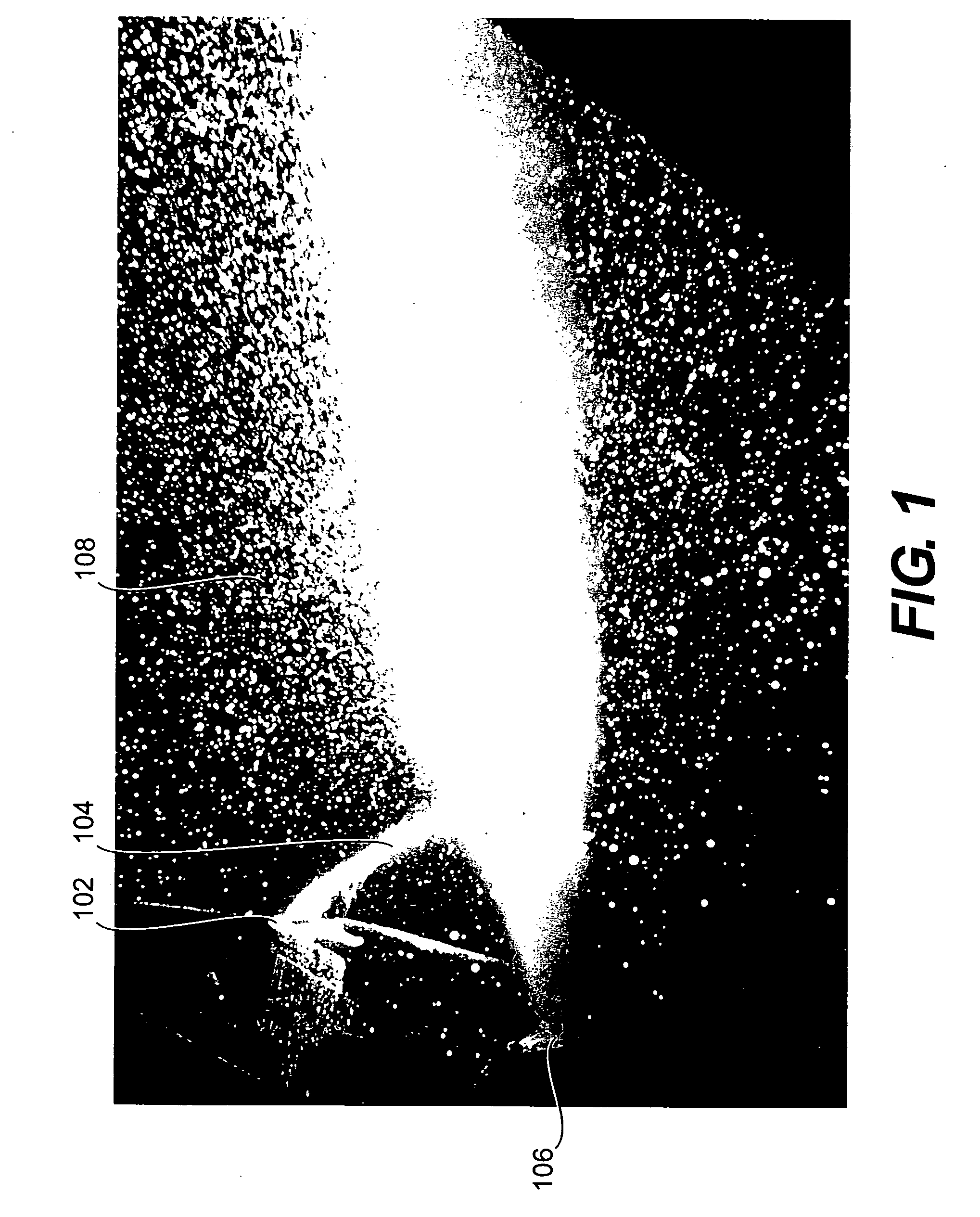
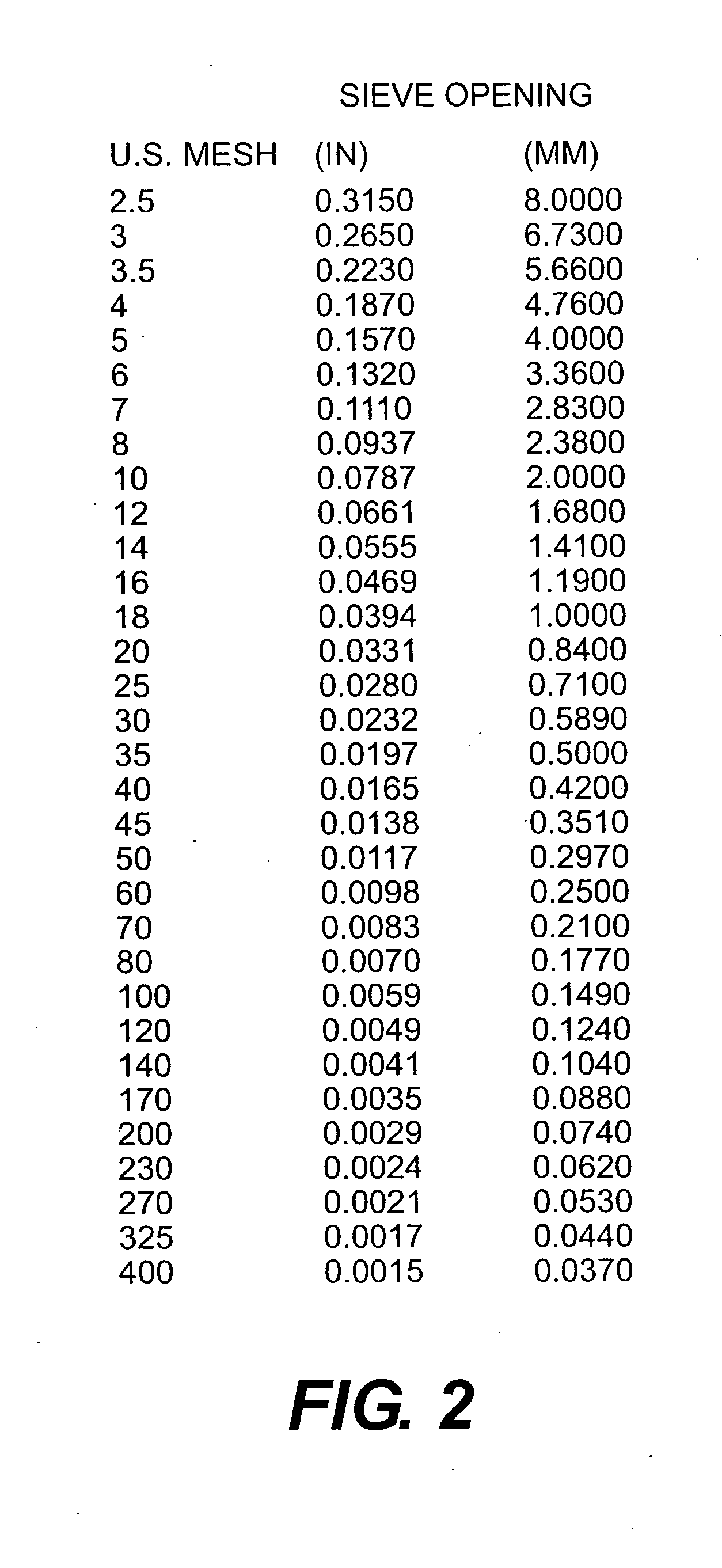
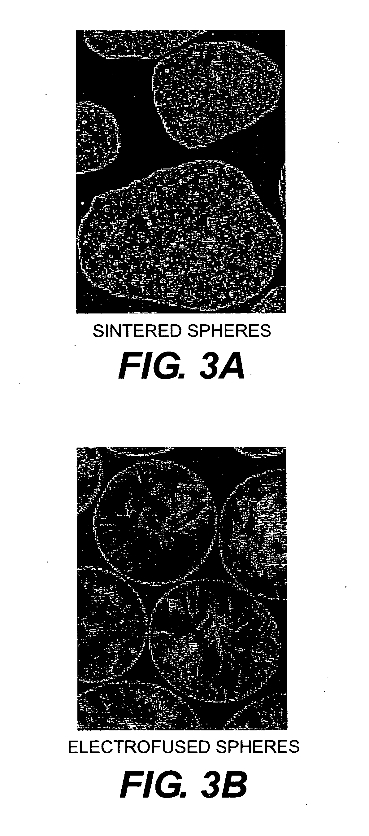
Image

Examples
example 1
Pure Alumina
[0058] A mixture of 1,000 kg of pure alumina and 4 kg of silica sand was melted in a lidded electrical arc furnace. The electrical arc furnace had a diameter of about 1.8 meters, a power of about 1.2 megawatts, and a voltage of about 172 volts. As soon as the mixture completely liquefied, the arc furnace was tilted and the molten mixture was poured from a pour spout to form a pour stream. Concurrently with the pouring, the pour stream was bessemerized with compressed air through a tube having an air nozzle directed at the pour stream. An air pressure of 8 bars was used, but other suitable pressures can be determined by those skilled in the art. The pressurized air caused individual droplets of the molten mixture to separate and rapidly solidify into spheres. The electrofused spheres were then collected in the bessemerizing chamber with a base comprising water-cooled steel plates. The electrofused spheres were then transported into a cooling tube by an air stream. After ...
example 2
[0059] 1,000 kg of bauxite having an alumina content of about 85% was melted in a lidded electrical arc furnace in the manner described above in connection with Example 1. Bauxite with higher alumina percentages may also be used. Because natural bauxite generally contains a sufficient amount of silica, the addition of silica sand was not necessary in this instance. The molten bauxite was then processed in the same manner as described above for the pure alumina mixture.
example 3
Mullite Containing Baddeleyite
[0060] 1,000 kg of mullite containing about 5% baddeleyite (ZrO2) was melted in a lidded electrical arc furnace. The electrofusion process of the molten mixture was the same as described above for the pure alumina mixture.
[0061] Table 1 below shows the physical properties of electrofused spheres that were obtained using the raw materials described above in the examples. It will be understood that these properties are merely illustrative and may vary depending on modifications to the electrofusion process and raw materials.
TABLE 1Example 1(aluminumExample 2Example 3oxide)(bauxite)(mullite)Apparent specific gravity (Hg)3.223.363.44Bulk density (g / cm3)2.12.12.1Specific surface area0.250.230.23(BET) (cm2 / g)Roundness (according to0.950.970.97Krumbein)Spherical form (according to0.980.980.98Krumbein)Grain crushing resistance356255(according to Vollstaedt on sieve35)(N)Porosity (digital image analysis)302426(%)
[0062] The Vollstaedt grain crushing resistanc...
PUM
| Property | Measurement | Unit |
|---|---|---|
| Fraction | aaaaa | aaaaa |
| Fraction | aaaaa | aaaaa |
| Fraction | aaaaa | aaaaa |
Abstract
Description
Claims
Application Information