
Programmable contact input apparatus and method of operating the same

a contact input and input device technology, applied in contact testing/inspection, protective switch details, instruments, etc., can solve problems such as inflexible previous devices, devices that cannot handle voltages within narrow ranges, and damage to control systems

Inactive Publication Date: 2014-10-23
GE INTELLIGENT PLATFORMS LTD
View PDF9 Cites 26 Cited by
  • Summary
  • Abstract
  • Description
  • Claims
  • Application Information

AI Technical Summary

Benefits of technology

This patent describes a technology that allows for a wide range of input voltage values, provides isolation, control of wetting current, internal checking of timing and communication, and a command / response interface. The technology uses multiple signal voltage spans or ranges, which can be obtained by either using multiple channels or a high resolution A / D converter. The technology also includes timing circuits within the contact input circuit to determine signal timing, making it easy to control the response of the contact input circuit to an external control system. Additionally, the technology utilizes an embedded A / D converter and control logic to improve safety integrity level (SIL) rating on the channel. This technology can be used in discrete parts like microcontrollers or mixed signal ASICs.

Problems solved by technology

Various problems have existed with previous approaches in monitoring contacts and other types of switching devices.
For example, the contacts need to be isolated from the control system, or damage to the control system may occur.
Also, the control system may need to handle a wide variety of different voltages, but previous devices could only handle voltages within narrow ranges.
Previous devices have also been inflexible in the sense that they cannot be easily changed or modified without circuit changes involving setting jumpers and / or adjusting resistors or other components to account for changes in the operating environment or conditions, or received voltages.
All of these problems have resulted in general dissatisfaction with previous approaches due to the need to supply many variations of the same circuit function with each set to a particular voltage and / or current.

Method used


Image

  • Programmable contact input apparatus and method of operating the same
  • Programmable contact input apparatus and method of operating the same
  • Programmable contact input apparatus and method of operating the same

Examples


Embodiment Construction

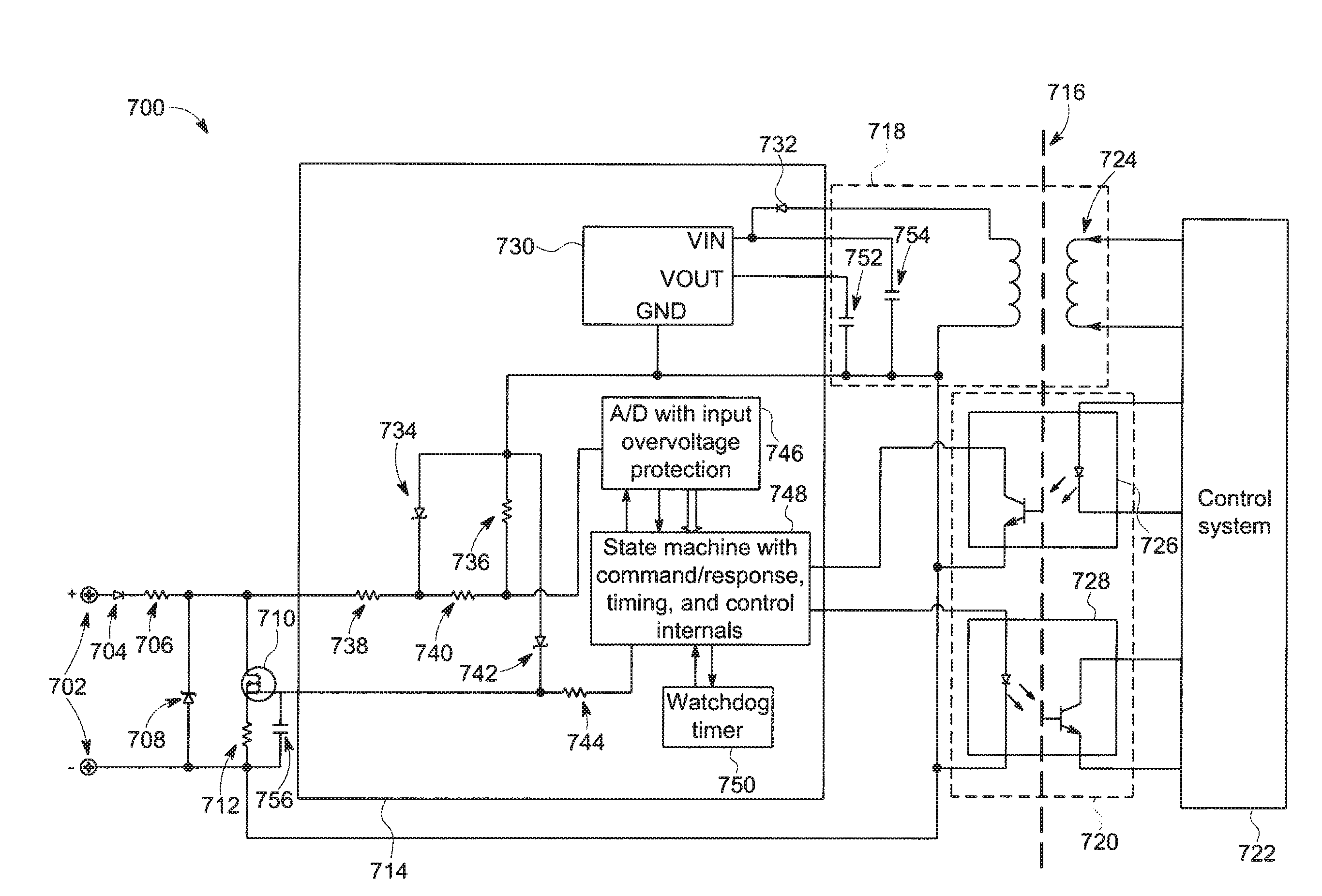
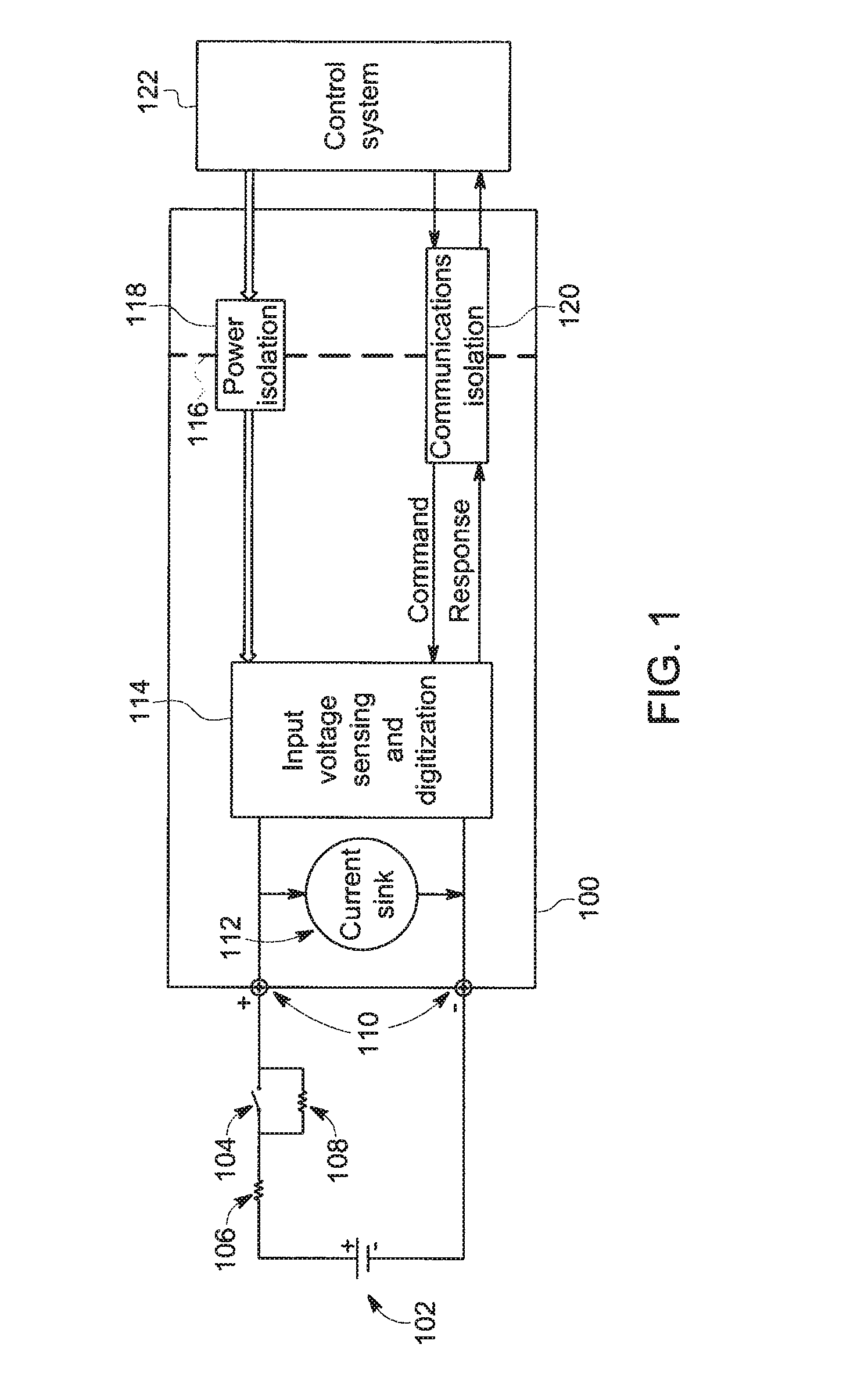
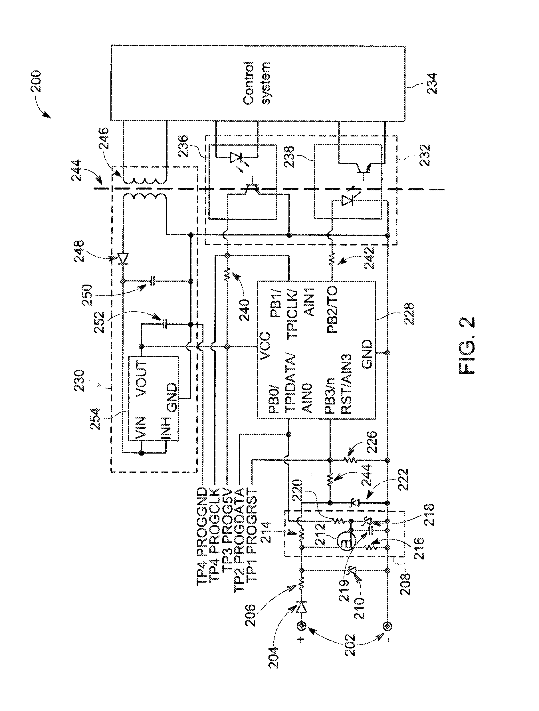
[0026]The approaches described herein provide for the programmed control of contact input settings across channels of a contact, switch, or discrete input module such as found in distributed control systems (DCS) or programmable logic controller (PLC)-based systems. The use of embedded control logic within a microcontroller or application specific integrated circuit (ASIC) is shown to allow a solution that provides programmed control of wetting current and voltage thresholds.

[0027]In one advantage of the present approaches, programmable thresholds for switch state decisions are provided. In another advantage, a programmable wetting current (based on switch voltage span) is provided. Improved self-test operations for fault detection are also obtained. The possible use of mixed signal ASIC to absorb channel components is also available. The possible insertion of mixed signal ASICs within a multi-die package to absorb isolation is also provided.

[0028]In some aspects, the present approa...


PUM


Abstract

At embedded control logic, electrical information with respect to a switching device is sensed. A decision is made as to an operation of the control logic based on the sensed information. The operation may be one or more of setting a wetting current or determining whether the electrical information is within an acceptable range.

Description

CROSS REFERENCE TO RELATED APPLICATIONS[0001]Utility application entitled “Apparatus and Method for Wetting Current Measurement and Control” naming as inventor Daniel Alley, and having attorney docket number 267012 (130838);[0002]Utility application entitled “Contact Input Apparatus Supporting Multiple Voltage Spans and Method of Operating the Same” naming as inventor Daniel Alley, and having attorney docket number 268616 (130841);[0003]are being filed on the same date as the present application, the contents of which are incorporated herein by reference in their entireties.BACKGROUND OF THE INVENTION[0004]1. Field of the Invention[0005]The subject matter disclosed herein relates to sensing information associated with switching devices and, more specifically, to sensing various types of this information over a wide range of operating conditions and values.[0006]2. Brief Description of the Related Art[0007]Different types of switching devices (e.g., electrical contacts, switches, and...

Claims


Application Information

Patent Timeline
IPC IPC(8): G01R31/327
CPCG01R31/327G01R31/3275H01H1/0015H01H2071/042
Inventor ALLEY, DANIEL MILTON
Owner GE INTELLIGENT PLATFORMS LTD
Learn More