Laser ignition system based diagnostics

a laser ignition and diagnostic technology, applied in the direction of engine starters, electric control, instruments, etc., can solve the problems of difficult to hold the engine in a selected position, high cost, and time-consuming diagnostics, and achieve the reduction of the need for costly and complex diagnostic tools, the accuracy of engine positioning, and the reliability of position-sensitive diagnostics.

Active Publication Date: 2014-10-23
FORD GLOBAL TECH LLC
View PDF25 Cites 16 Cited by
  • Summary
  • Abstract
  • Description
  • Claims
  • Application Information

AI Technical Summary

Benefits of technology

[0006]In this way, an electric motor of a hybrid vehicle system can be used during a service mode to assist in engine positioning for diagnostics. By operating the motor to rotate and hold the engine at a specified position, accuracy of engine positioning is improved

Problems solved by technology

The inventors herein have recognized that some of the diagnostics can be time, cost, and complexity-intensive.
In addition, for diagnostics that are sensitive to the position of the engine, small fluc

Method used


Image

  • Laser ignition system based diagnostics
  • Laser ignition system based diagnostics
  • Laser ignition system based diagnostics

Examples


Embodiment Construction

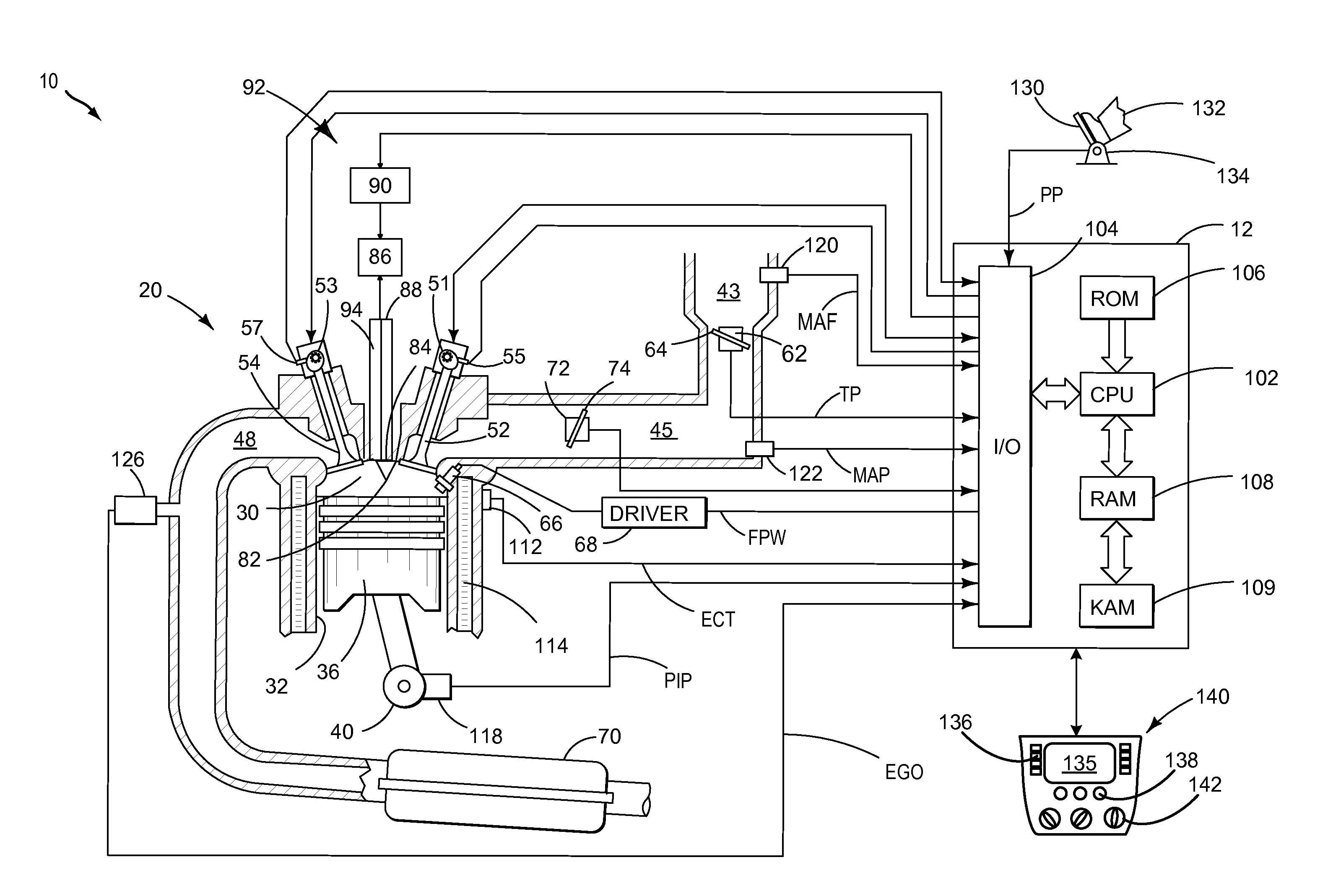
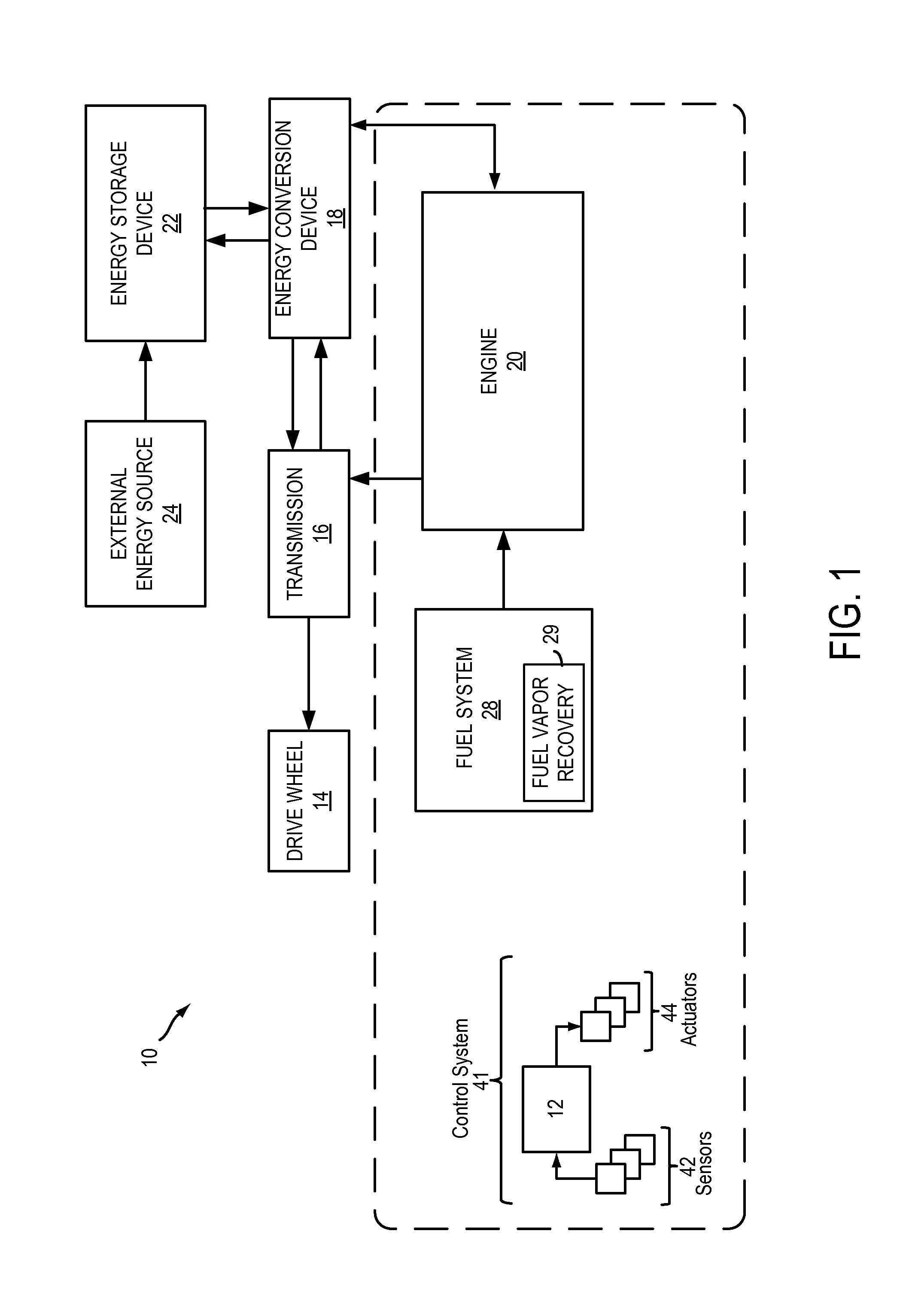
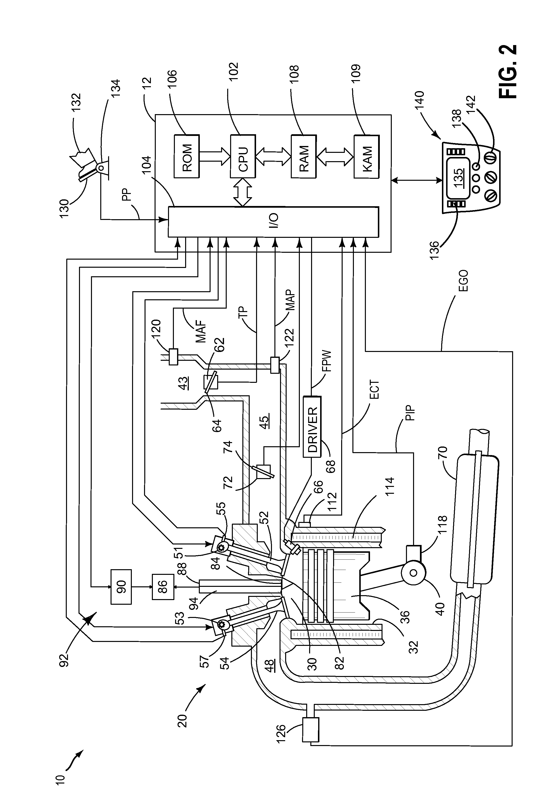
[0013]Methods and systems are provided for enabling visual inspection of an engine cylinder of a hybrid vehicle using an engine laser ignition system, such as the systems of FIG. 1-3. Low power laser pulses emitted by the laser ignition system (FIG. 3) can be used to generate images of the inside of the cylinder. The images may then be displayed on a center-console of the vehicle. An engine controller may be configured to perform a control routine, such as the routine of FIG. 4, to operate the laser ignition device in a diagnostic mode during non-combusting conditions. Images generated by a photodetector of the laser ignition system may be displayed to a service provider (or mechanic) on the center-console and used by the service-provider to infer cylinder damage. One or more knobs of the center-console may be activated when operating in the diagnostic mode for making refinements to the position of the engine that improve a view of the interior of the cylinder. In this way, engine d...


PUM


Abstract

Methods and systems are provided for enabling engine diagnostics, including visual inspections of an engine cylinder, using existing hardware from a laser ignition system. Light pulses from a laser ignition device are received at a photodetector during non-combusting conditions and used to generate images of an inside of the cylinder that can be assessed by a service technician. An electric motor of the vehicle system can be used during a service mode of the vehicle to rotate the engine to, and hold the engine at, specified engine positions that enable the technician to perform selected diagnostic tests.

Description

FIELD[0001]The present application relates to methods and systems for diagnosing an engine using a laser ignition system.BACKGROUND AND SUMMARY[0002]Vehicle engines may need to be intermittently serviced by a mechanic for diagnostic purposes. Diagnostics may involve visually inspecting engine components (for example, to identify scoring damage, camshaft alignment issues, etc.), rotating an engine to a selected position to identify component damage (for example, to detect hydro-lock) and / or spinning an engine (for example, to perform vacuum tests).[0003]The inventors herein have recognized that some of the diagnostics can be time, cost, and complexity-intensive. In addition, for diagnostics that are sensitive to the position of the engine, small fluctuations in the engine position can substantially corrupt the result of the diagnostics. Further, it may be difficult to hold the engine in a selected position due to compression forces in the engine.[0004]In view of the above issues, the...

Claims


Application Information

Patent Timeline
IPC IPC(8): B60W20/00B60W10/08B60W10/06
CPCB60W20/50Y10S903/93B60W10/08B60W10/06B60W2510/0685B60Y2300/64F02D35/022F02D41/009F02D41/22F02N19/005F02P23/04Y02T10/62
Inventor MARTIN, DOUGLAS RAYMONDMARTIN, LAUREN ANGELINA
Owner FORD GLOBAL TECH LLC
Why Eureka
Try Eureka