Harmonic uniflow engine

Active Publication Date: 2014-10-30
LAWRENCE LIVERMORE NAT SECURITY LLC
View PDF5 Cites 7 Cited by
  • Summary
  • Abstract
  • Description
  • Claims
  • Application Information

AI Technical Summary

Benefits of technology

[0008]One aspect of the present invention includes a harmonic uniflow engine comprising: a cylinder having a cylinder axis; a piston head reciprocable in the cylinder and together enclosing an expansion chamber, wherein the cylinder has an inlet at an inlet end fluidically connected to the expansion chamber and an outlet at a removed location from the inlet end; an intake header in fluidic communication with the inlet for channeling working fluid from a pressurized fluid source into the expansion chamber; an inlet valve for controlling the flow of working fluid from the intake header into the expansion chamber to effect a power stroke of the engine, said inlet valve comprising an inlet valve head and a resiliently biasing member arranged together as a harmonic oscillator so that the inlet valve head is moveable against an equilibrium restoring force of the resiliently biasing member from an unbiased equilibrium position located in the intake header to a biased closed position occluding the inlet, and so that upon releasing from the closed position the inlet valve head undergoes a single oscillation past the equilibrium position to an oppositely biased maximum open position and returns to a biased return position between the closed and equilibrium positions to choke the flow of working fluid and produce a pressure drop across the inlet valve causing the inlet valve to close, wherein the piston head is reciprocable to a venting position which fluidically connects the expansion chamber to the outlet for controlling the periodic venting of working fluid out from the expansion chamber, and periodic return means operably connected to the piston head to effect a return stroke of the engine after each power stroke.
[0009]Another aspect of the present invention includes a uniflow energy conversion system comprising: a cylinder having a cylinder axis; a piston head reciprocable in the cylinder and together enclosing a chamber, wherein the cylinder has a first port at a first end fluidically connected to the chamber and a second port at a second end opposite the first end; a valve for controlling the flow of working fluid between the first port and the chamber, said valve comprising a valve head and a resiliently biasing member arranged together so that the valve head is moveable against an equilibrium restoring force of the resiliently biasing member from an unbiased equilibrium position to a biased closed position occluding the first port; and periodic means operably connected to the piston head to effect at least one of two reciprocation strokes thereof, wherein the piston head is adapted to rotate about a pivot axis as it reciprocates in the cylinder so: that during one of the two reciprocation strokes the piston head maintains a seal with the cylinder to inhibit blow-by past the piston head; and during the other one of the two reciprocation strokes a pair of pivotable ends of the piston head on opposite sides of the pivot axis are radially displaced away from the cylinder so as to form blow-by channels between the pivotable ends and the cylinder which fluidically connect the chamber to the second port, for controlling the periodic flow of working fluid between the chamber and the second port.
[0010]Another aspect of the present invention includes a uniflow engine comprising: a cylinder having a cylinder axis; a piston head reciprocable in the cylinder and together enclosing an expansion chamber, wherein the cylinder has an inlet at an inlet end fluidically connected to the expansion chamber and an outlet at an outlet end opposite the inlet end; an intake header in fluidic communication with the inlet for channeling working fluid from a pressurized fluid source into the expansion chamber; an inlet valve for controlling the flow of working fluid from the intake header into the expansion chamber to effect a power stroke of the engine, said inlet valve comprising an inlet valve head and a resiliently biasing member arranged together as a harmonic oscillator so that the inlet valve head is moveable against an equilibrium restoring force of the resiliently biasing member from an unbias

Problems solved by technology

There have been a number of technical challenges in the art of uniflow engines, such as the need to maintain a significant minimum cylinder clearance space, in order to avoid damage produced from overly recompressing steam as the piston approaches TDC.
On the other hand, on the exhaust stroke, without recompressing steam all the way to the pressure of the incoming steam, and with a significant minimum cylinder clearance space, the resulting highly non isentropic, rapid inrush of high pressure steam at the time the inlet valve opens and the clearance space fills is detrimental to achieving hig

Method used


Image

  • Harmonic uniflow engine
  • Harmonic uniflow engine
  • Harmonic uniflow engine

Examples


first example embodiment

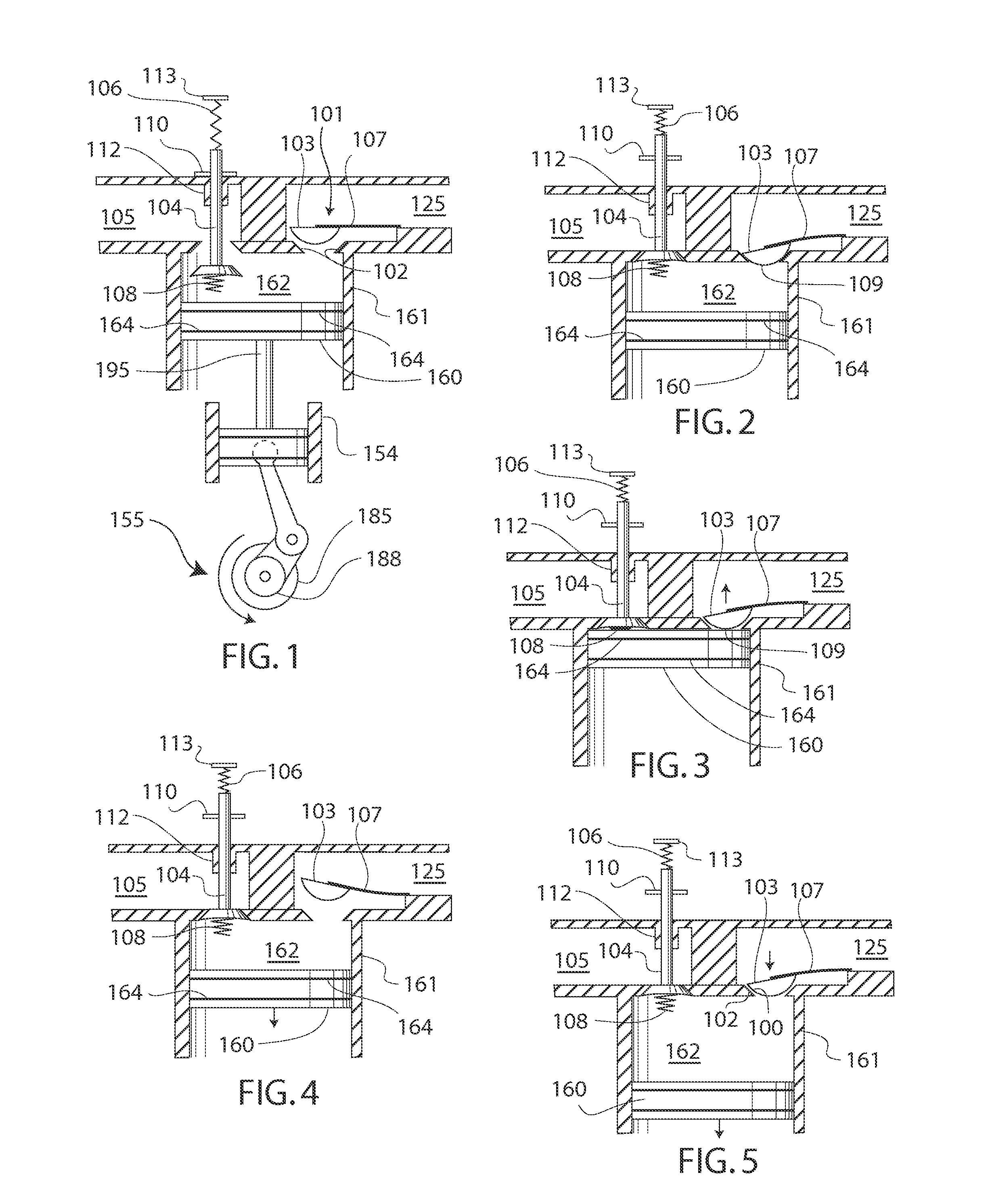
[0049]Turning now to the drawings, FIGS. 1-5 show a first exemplary system of the engine of the present invention. In particular, FIG. 1 shows the harmonic engine in a static, non-operational state such as typically seen just prior to startup, and FIGS. 2-5 show the harmonic engine in various dynamic states of its two-stroke operation. The harmonic engine is shown comprising the following components and sub-assemblies. First a reciprocating-piston expander is shown comprising an expander cylinder 161 having an inlet and an outlet. The expander also includes a piston head 160 axially slidable in the expander cylinder and together enclosing an expansion chamber 162 accessible by the inlet and the outlet. Also the expander includes an intake header 125 in fluidic communication with the inlet for channeling working fluid from a pressurized fluid source into the expansion chamber, and an exhaust header 105 in fluidic communication with the outlet for channeling working fluid exhausted ou...

second example embodiment

Normal Operation of Second Example Embodiment

[0087]The operation of the second embodiment under nominal or lower pressure conditions is very much as described above for the first embodiment. The minimal volume of the expansion chamber at TDC, dictates that the amount of working fluid that must be admitted through the inlet valve to raise the pressure within the cylinder to that of the supply is minimal, and the pressure jump as the piston approaches TDC can be achieved in minimal time. This is advantageous for achieving higher efficiency and power.

High Pressure Overdrive Operation

[0088]The operation of the second embodiment under high supply pressure conditions changes significantly, and the contrast with nominal pressure operation is shown in FIG. 10. In this figure, the motion of inlet valve 401, outlet valve 404, piston 460 and cylinder pressure 472 are shown as a function of crankshaft angle. The motion of the inlet valve for a single cycle of free oscillation (neglecting aerody...

third example embodiment

Timing of Third Example Embodiment

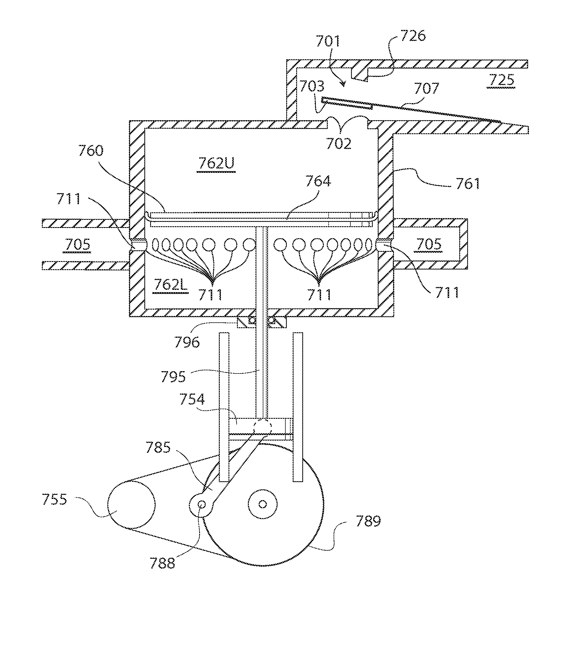
[0100]A timing diagram for the wobble-piston embodiment is displayed in FIG. 14. Curves in this figure show the relative positions of the inlet valve, the outlet valve and the center of the top of the wobble-piston. The pressure 270 within expansion chamber 262 is also displayed as a function of the crankshaft angle. Starting at 0° in this cycle, the wobble piston motion is such that the phasing of the opening of inlet valve 201, shown by arrow 243, may be designed to coincide precisely with the TDC position of the wobble piston. In contrast to a purely axially moving piston, in which the instantaneous velocity of the piston vanishes at TDC, for the wobble-piston, the instantaneous velocity of the right hand side, bearing the inlet valve opening protrusion, does not vanish at TDC. This important distinction allows precise and reliable timing of the opening of the inlet valve. Then, in the initial portion of the inlet valve opening cycle, just after ...


PUM


Abstract

A reciprocating-piston uniflow engine includes a harmonic oscillator inlet valve capable of oscillating at a resonant frequency for controlling the flow of working fluid into the engine. In particular, the inlet valve includes an inlet valve head and a spring arranged together as a harmonic oscillator so that the inlet valve head is moveable from an unbiased equilibrium position to a biased closed position occluding an inlet. When released, the inlet valve head undergoes a single oscillation past the equilibrium position to a maximum open position and returns to a biased return position close to the closed position to choke the flow and produce a pressure drop across the inlet valve causing the inlet valve to close. In other embodiments, the harmonic oscillator arrangement of the inlet valve enables the uniflow engine to be reversibly operated as a uniflow compressor.

Description

CROSS-REFERENCE TO RELATED APPLICATIONS[0001]This application is a continuation-in-part of U.S. patent application Ser. No. 13 / 221,783 filed Aug. 30, 2011, which claims the benefit of U.S. provisional application No. 61 / 378,327 filed Aug. 30, 2010, both of which are incorporated by reference herein.FEDERALLY SPONSORED RESEARCH OR DEVELOPMENT[0002]The United States Government has rights in this invention pursuant to Contract No. DE-AC52-07NA27344 between the United States Department of Energy and Lawrence Livermore National Security, LLC for the operation of Lawrence Livermore National Laboratory.BACKGROUND OF THE INVENTION[0003]A. Technical Field[0004]This invention generally relates to pressure activated engines and compressors. More particularly, this invention is a reciprocating-piston engine having a harmonic oscillator valve controlling the admission of a pressurized expansible fluid into an expansion chamber and an outlet controlled by the motion of the piston allowing the exh...

Claims


Application Information

Patent Timeline
IPC IPC(8): F01C21/18F04B49/22F15B13/02F04B53/14
CPCF01C21/18F15B13/027F04B49/22F04B53/146F01L23/00F01L3/205F01B17/02F01B25/02
Inventor BENNETT, CHARLES L.
Owner LAWRENCE LIVERMORE NAT SECURITY LLC
Why Eureka
Try Eureka