Method and system for producing a synthesis gas in an oxygen transport membrane based reforming system with recycling of the produced synthesis gas

a technology of oxygen transport membrane and synthesis gas, which is applied in the direction of oxygen/ozone/oxide/hydroxide, chemistry apparatus and processes, organic chemistry, etc., can solve the problems of complex installation, add complexity and capital and operating costs to the overall process, and often require preheating of the hydrocarbon feed to similarly high temperatures

Active Publication Date: 2014-10-30
PRAXAIR TECH INC
View PDF2 Cites 35 Cited by
  • Summary
  • Abstract
  • Description
  • Claims
  • Application Information

AI Technical Summary

Benefits of technology

[0013]The present invention may be characterized as a method for producing a synthesis gas in an oxygen transport membrane based reforming system, which comprises two reactors, a reforming catalyst containing reformer reactor and an oxidation catalyst containing oxygen transport membrane reactor preferably in the form of tubes, the method comprising the steps of: (i) separating an oxygen containing stream into an oxygen permeate and an oxygen depleted retentate stream using a plurality of oxygen transport membrane elements disposed in the oxygen transport membrane based reforming system; (ii) reacting a hydrogen containing stream contacting a permeate side of the oxygen transport membrane elements with the oxygen permeate to generate a reaction product stream and heat; (iii) pre-heating a hydrocarbon containing feed stream and combining the pre-heated hydrocarbon containing feed stream with steam and then with a portion of the reaction product stream to produce a combined feed stream having a steam to carbon ratio between about 1.6 and 3.0 and a temperature between about 500° C. and 750° C.; (iv) reforming the combined feed steam in the at least one catalyst containing reforming reactor in the presence of the catalyst and the heat generated by the reaction of the hydrogen containing stream and permeated oxygen to produce a synthesis gas stream, the at least one catalyst containing reforming reactor disposed proximate the oxygen transport membrane elements; and (v) recycling a portion of the synthesis gas stream to the permeate side of the plurality of oxygen transport membrane elements to form all or a part of the hydrogen containing stream wherein the recycled portion of the synthesis gas is maintained at a temperature of less than about 400° C. or a temperature of greater than about 800° C. such that the oxygen transport membrane based reforming system is substantially free of metal dusting corrosion.

Problems solved by technology

However, both the ATR as well as POx processes require separate air separation units (ASU) to produce high-pressure oxygen, which adds complexity as well as capital and operating cost to the overall process.
As can be appreciated, the conventional methods of producing a synthesis gas such as have been discussed above are expensive and require complex installations.
The problem with all of these oxygen transport membrane based systems is that because such oxygen transport membranes need to operate at high temperatures of around 900° C. to 1100° C., preheating of the hydrocarbon feed to similarly high temperatures is often required.
Where hydrocarbons such as methane and higher order hydrocarbons are subjected to such high temperatures, excessive carbon formation will occur in the feed stream, especially at high pressures and low steam to carbon ratios.
The carbon formation problems are particularly severe in the above-identified prior art oxygen transport membrane based systems.
Other problems that arise with the prior art oxygen transport membrane based reforming systems are the cost of the oxygen transport membrane modules and the lower than desired durability, reliability and operating availability of such oxygen transport membrane based reforming systems.
These problems are the primary reasons that oxygen transport membranes based reforming systems have not been successfully commercialized.

Method used


Image

  • Method and system for producing a synthesis gas in an oxygen transport membrane based reforming system with recycling of the produced synthesis gas
  • Method and system for producing a synthesis gas in an oxygen transport membrane based reforming system with recycling of the produced synthesis gas
  • Method and system for producing a synthesis gas in an oxygen transport membrane based reforming system with recycling of the produced synthesis gas

Examples


Embodiment Construction

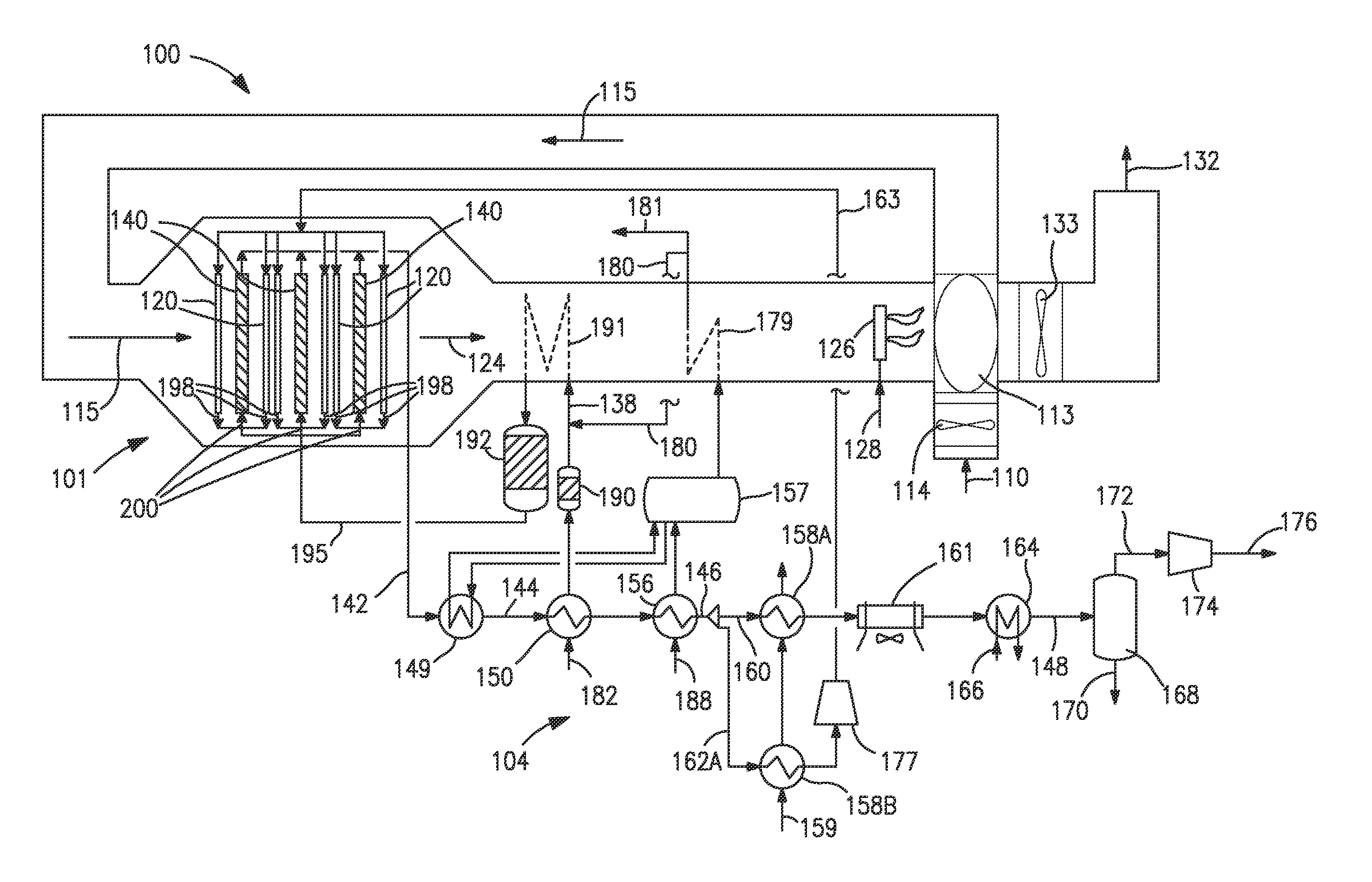
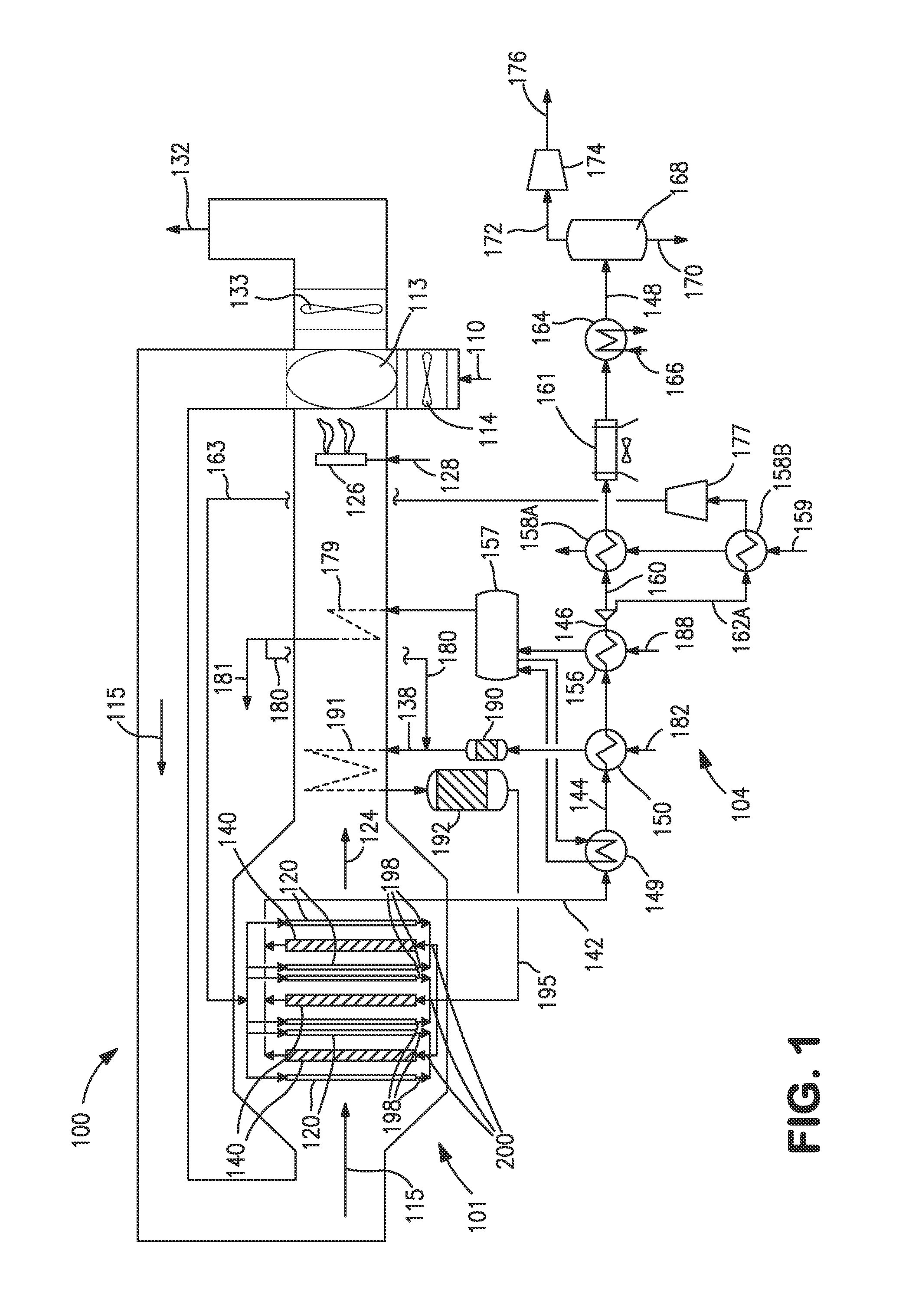
[0026]Turning now to FIG. 1, there is shown a schematic illustration of an embodiment of an oxygen transport membrane based reforming system 101 and assembly 100 in accordance with the present invention. As seen therein, an oxygen containing stream 110, such as air, is introduced to the system by means of a blower or fan 114 into a heat exchanger 113 for purposes of preheating the oxygen containing stream 110. Heat exchanger 113 is preferably a high efficiency, cyclic and continuously rotating regenerator disposed in operative association with the oxygen containing stream 110 and the heated retentate stream 124. The heated and oxygen depleted retentate stream 124 can optionally be introduced into a duct burner region containing duct burner 126 and used to support combustion of a supplemental fuel stream 128 to produce supplemental heat introduced into the continuously rotating regenerator 113 to preheat the oxygen containing stream 110. Alternatively, the duct burner may also be dis...


PUM

PropertyMeasurementUnit
temperatureaaaaaaaaaa

Abstract

A method and system for producing a synthesis gas in an oxygen transport membrane based reforming system that utilizes a combined feed stream having a steam to carbon ratio between about 1.6 and 3.0 and a temperature between about 500° C. and 750° C. The combined feed stream is comprised a pre-reformed hydrocarbon feed, superheated steam, and a reaction product stream created by the reaction of a hydrogen containing stream reacted with the permeated oxygen at the permeate side of the oxygen transport membrane elements and wherein the hydrogen containing stream is a recycled portion of the synthesis gas.

Description

CROSS REFERENCE TO RELATED APPLICATIONS[0001]This application claims priority to and the benefit of U.S. provisional patent application Ser. No. 61 / 816,297 filed on Apr. 26, 2013, the disclosure of which is incorporated by reference herein.FIELD OF THE INVENTION[0002]The present invention relates to a method and system for producing a synthesis gas in an oxygen transport membrane based reforming system, and more particularly, a method and system for producing a synthesis gas in an oxygen transport membrane based reforming system that utilizes a combined feed stream comprised a pre-reformed hydrocarbon feed, superheated steam, and a reaction product stream created by the reaction of a hydrogen containing stream reacted with the permeated oxygen at the permeate side of oxygen transport membrane elements, wherein the hydrogen containing stream is a recycled portion of the synthesis gas.BACKGROUND[0003]Synthesis gas containing hydrogen and carbon monoxide is used for a variety of indust...

Claims


Application Information

Patent Timeline
Patent Type & Authority Applications(United States)
IPC IPC(8): C01B3/38
CPCC01B3/382C01B3/384C01B13/0251C01B2203/0233C01B2203/0283C01B2203/043C01B2203/0822C01B2203/0827C01B2203/142Y02P20/10
Inventor CHAKRAVARTI, SHRIKARKROMER, BRIAN R.CRAIGIE, KEITH A.KELLY, SEAN M.LI, JUAN
Owner PRAXAIR TECH INC
Why Eureka
Try Eureka