Piezoelectric power converter with bi-directional power transfer

Inactive Publication Date: 2014-11-13
NOLIAC
View PDF11 Cites 14 Cited by
  • Summary
  • Abstract
  • Description
  • Claims
  • Application Information

AI Technical Summary

Benefits of technology

[0038]conducting both forward current and reverse current during a single cycle of the transformer output signal. As previously explained, the net power transferred to the output voltage may be controlled in either a step-wise or in a substantially continuous manner by a corresponding control of the relative length between the first and second periods of the same cycle of the transformer ou

Problems solved by technology

Traditional piezoelectric transformer based power converters are only capable of supplying power in one direction, from an input voltage/power source to a DC or AC output of the power converter.
The small optimum frequency band of operation and the need for a matched load make output voltage regulation difficult without sacrificing efficiency of the piezoelectric based power converter.
Likewise in situations where the excitation frequency is substantially fixed, traditional output voltage control techniques based frequency modulation or pulse width modulation of the input drive signal c

Method used


Image

  • Piezoelectric power converter with bi-directional power transfer
  • Piezoelectric power converter with bi-directional power transfer
  • Piezoelectric power converter with bi-directional power transfer

Examples


Example

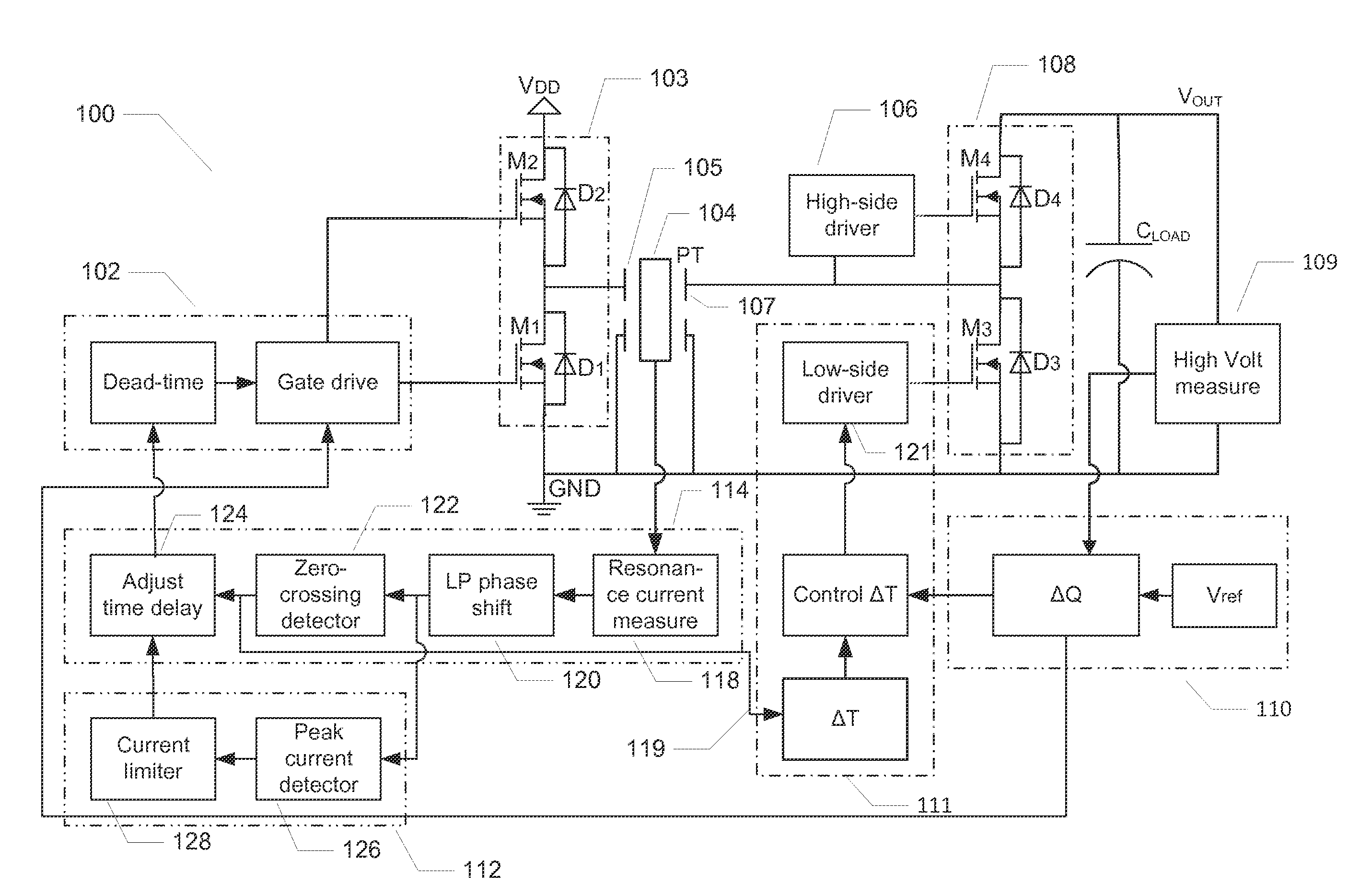
[0048]The below appended detailed description of embodiments of the present invention is directed to bi-directional piezoelectric power converters for voltage step-up or voltage multiplication aimed at generating high DC output voltages such as output voltages from several hundred Volts to several thousand Volts. However, the skilled person will understand that the below described embodiments are highly useful for other types of applications such as step-down and low voltage piezoelectric power converters requiring high power conversion efficiency.

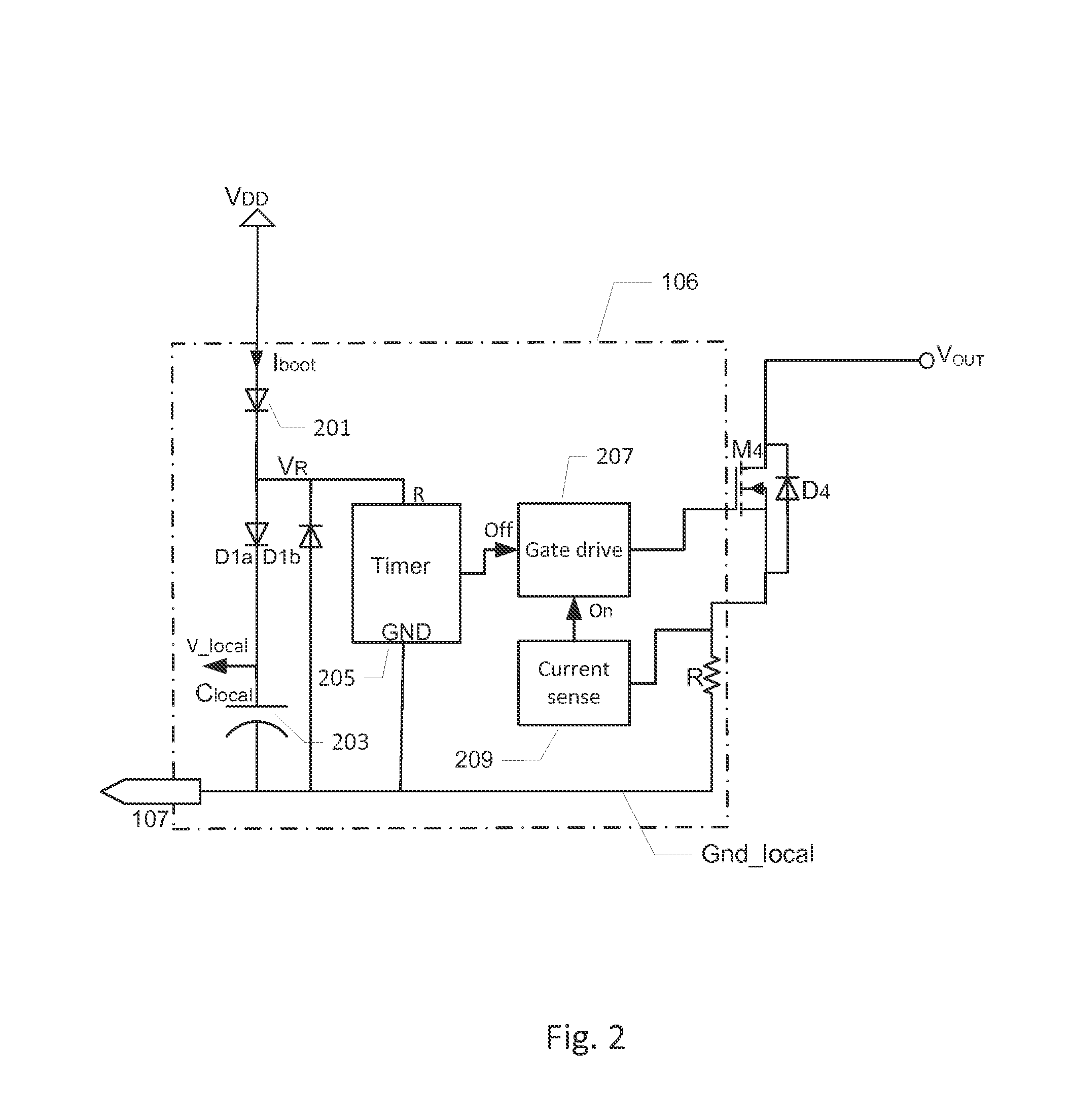
[0049]FIG. 1 shows a schematic block diagram of a bi-directional piezoelectric power converter 100 in accordance with a first embodiment of the invention. The bi-directional piezoelectric power converter 100 comprises a piezoelectric transformer, PT, 104. The piezoelectric transformer, PT, 104 has a first input electrode 105 electrically coupled to an input or primary section of the bi-directional piezoelectric power converter 100 and a se...


PUM


Abstract

The present invention relates to a bi-directional piezoelectric power converter comprising a piezoelectric transformer. The piezoelectric transformer comprises an input electrode electrically coupled to a primary section of the piezoelectric transformer and an output electrode electrically coupled to an output section of the piezoelectric transformer to provide a transformer output signal. A bi-directional switching circuit is coupled between the output electrode and a DC or AC output voltage of the power converter. Forward and reverse current conducting periods of the bi-directional switching circuit is based on the input drive signal or the transformer output signal such that a forward current is conducted from the output electrode through the bi-directional switching circuit to the DC or AC output voltage in a first state to charge the DC or AC output voltage. In a second state, a reverse current is conducted through the bi-directional switching circuit from the DC or AC output voltage to the output electrode to discharge the DC or AC output voltage and return power to the primary section of the piezoelectric transformer.

Description

[0001]The present invention relates to a bi-directional piezoelectric power converter comprising a piezoelectric transformer. The piezoelectric transformer comprises an input electrode electrically coupled to a primary section of the piezoelectric transformer and an output electrode electrically coupled to an output section of the piezoelectric transformer to provide a transformer output signal. A bi-directional switching circuit is coupled between the output electrode and a DC or AC output voltage of the power converter. Forward and reverse current conducting periods of the bi-directional switching circuit is based on the input drive signal or the transformer output signal such that a forward current is conducted from the output electrode through the bi-directional switching circuit to the DC or AC output voltage in a first state to charge the DC or AC output voltage. In a second state, a reverse current is conducted through the bi-directional switching circuit from the DC or AC ou...

Claims


Application Information

Patent Timeline
IPC IPC(8): H02M3/335
CPCH02M3/33584H02M3/3385H02M7/537Y02B70/10H02M1/0058H10N30/804H02M3/33592
Inventor MEYER, KASPAR SINDINGRODGAARD, MARTIN SCHOLERANDERSEN, MICHAEL ANDREAS ESBERNANDERSEN, THOMAS
Owner NOLIAC
Why Eureka
Try Eureka