Decoding device and decoding method

Active Publication Date: 2014-11-13
PANASONIC INTELLECTUAL PROPERTY MANAGEMENT CO LTD
View PDF3 Cites 0 Cited by
  • Summary
  • Abstract
  • Description
  • Claims
  • Application Information

AI Technical Summary

Benefits of technology

[0021]The present invention has been made in order to solve the problems described above and an object thereof is to provide a decoding de

Problems solved by technology

In recent years, due to higher density of optical disks, a shortest mark length that is a length of a shortest recording mark is approaching a limit of optical resolution and an increase in intersymbol interferences and degradation of SNRs (Signal Noise Rates) are becoming more noticeable.
As the density of optical disks become higher, intersymbol interferences and SNR degradation become more problematic.
With the increase in information traffic, there is an apparent upward trend in inputted optical power and a physical limit of optical fibers where non-linear optical effects and thermal destruction occur is quickly approaching.
As a result, the number of states increases to 466 and an enormous amount of processing becomes necessary.
However, reducing the length of a PR class increases high frequency gain, and causes a significant amplification of noise, a deterioration of SNR, and a degradation of decodi

Method used


Image

  • Decoding device and decoding method
  • Decoding device and decoding method
  • Decoding device and decoding method

Examples


Example

First Embodiment

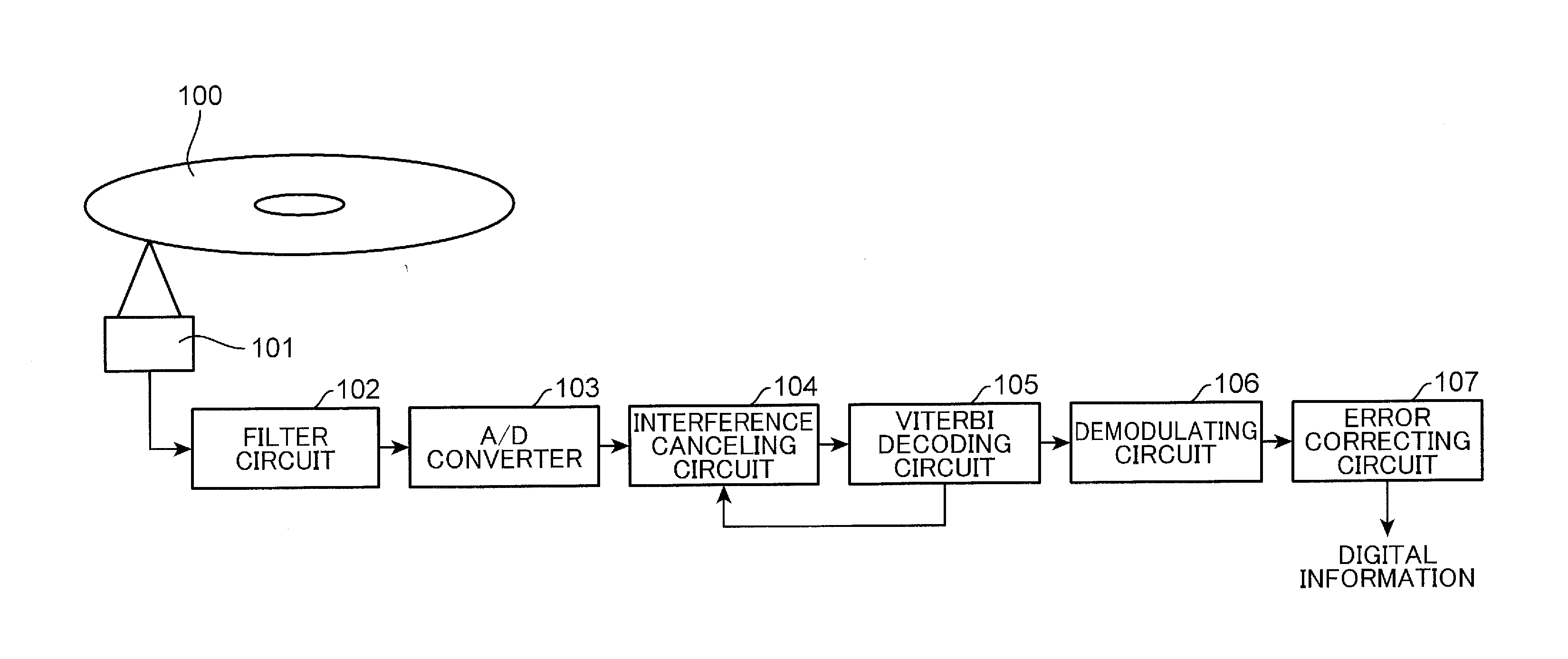
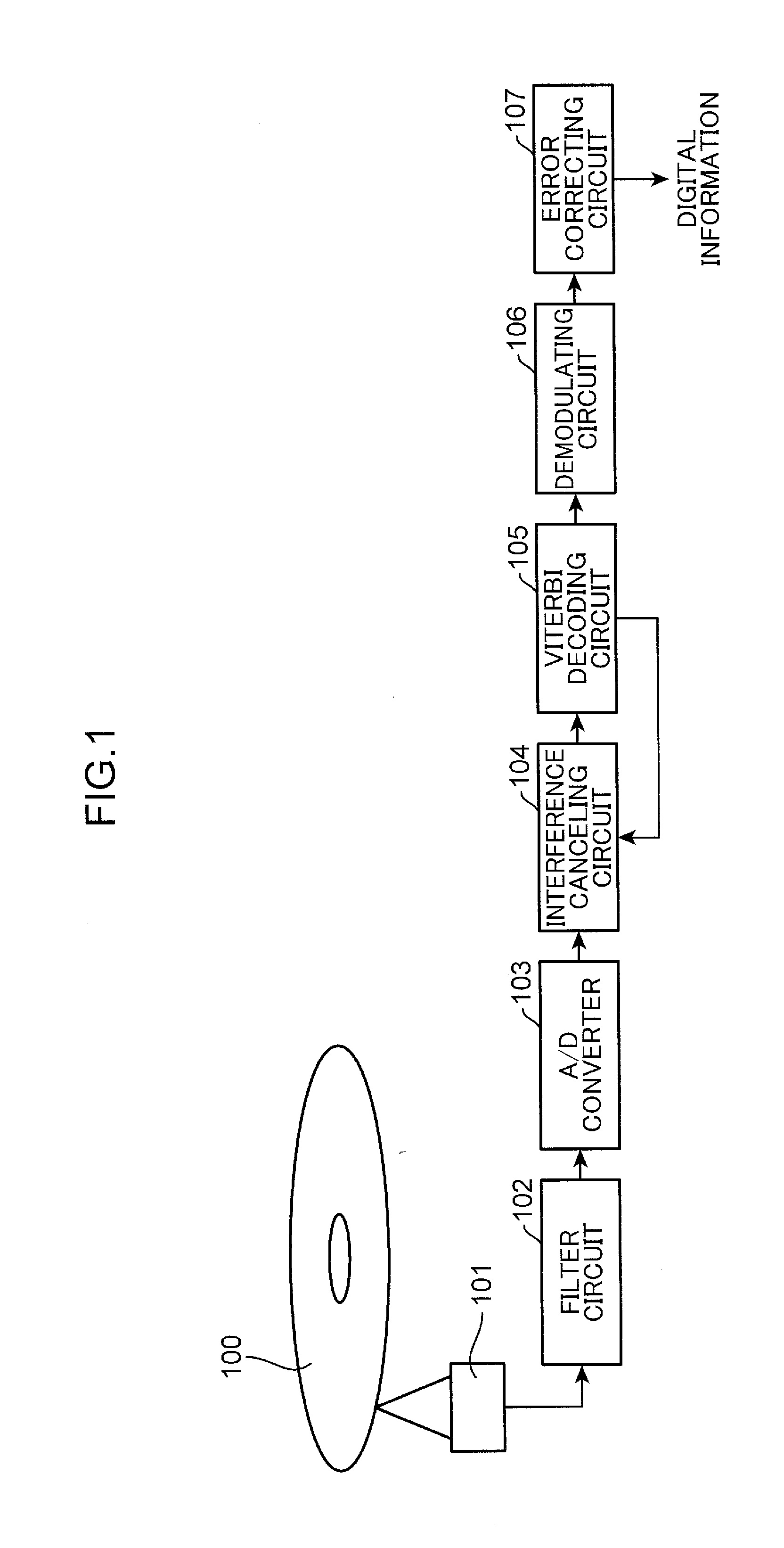
[0068]FIG. 1 is a diagram showing a configuration of an optical disk device according to a first embodiment of the present invention. Moreover, FIG. 1 shows a configuration of a portion related to a processing system which reproduces digital information from an optical disk 100. The optical disk device shown in FIG. 1 comprises an optical pickup 101, a filter circuit 102, an A / D converter 103, an interference canceling circuit 104, a Viterbi decoding circuit 105, a demodulating circuit 106, and an error correcting circuit 107.

[0069]On the optical disk 100, a recording mark is formed on a track in accordance with a recorded code obtained by performing error correction encoding according to a predetermined error correction encoding system and modulation encoding according to a predetermined modulation system on digital information. A reproduction process for reproducing recorded digital information is performed by utilizing the fact that the amount of reflected light w...

Example

Second Embodiment

[0110]FIG. 13 is a diagram showing a configuration of an optical communication device according to a second embodiment of the present invention. The optical communication device comprises a transmitter 1007, an optical fiber 1003, and a receiver 1008.

[0111]The transmitter 1007 which transmits transmission information comprises an error correction encoding circuit 1000, a modulating circuit 1001, and an optical modulating circuit 1002. The error correction encoding circuit 1000 performs error correction encoding on transmission information to be transmitted. The modulating circuit 1001 digitally modulates the transmission information subjected to error correction encoding using a modulation system such as ASK (amplitude shift keying) or PSK (phase shift keying), and outputs the digitally modulated transmission information as a digital code. The optical modulating circuit 1002 generates an optical signal waveform having intensity or a phase of light with a predetermin...

Example

Third Embodiment

[0125]First, before describing a decoding device and a decoding method according to a third embodiment of the present invention, problems found in conventional art will be described.

[0126]In recent years, due to higher density of optical disks, a shortest mark length that is a length of a shortest recording mark is approaching a limit of optical resolution and an increase in intersymbol interferences and degradation of SNRs (Signal Noise Rates) are becoming more noticeable. In consideration thereof, a PRML (Partial Response Maximum Likelihood) system is generally used as a signal processing method.

[0127]The PRML system is a technique that combines a partial response (PR) with maximum likelihood decoding (ML) and is a system which selects a most likely signal sequence from a reproduced waveform on the premise that a known intersymbol interference is to occur. Therefore, the PRML system is known for improved decoding performance as compared to conventional level judgme...


PUM


Abstract

A decoding device includes: an interference canceling circuit (104) which extracts, from states of 2K-number (where K is a natural number) of detected signals that are likely within a range of K bit width where an interference between bits of the digital information occurs due to predetermined frequency characteristics, most likely 2M-number (where M is a natural number) of detected signals respectively corresponding to states of 2M-number of detected signals which exist within a range of M bit width that is included in the range of K bit width; and a Viterbi decoding circuit (105) which generates a decoded signal by calculating differences between the 2M-number of detected signals extracted by the interference canceling circuit (104) and expectation signals respectively corresponding to the 2M-number of detected signals and also by selecting a transition sequence of a state of a detected signal for which the calculated difference is smallest.

Description

TECHNICAL FIELD[0001]The present invention relates to a decoding device and a decoding method for decoding digital information based on a reproduced signal detected from a recording medium such as an optical disk or on a reception signal received via a communication medium such as an optical fiber.BACKGROUND ART[0002]In recent years, due to higher density of optical disks, a shortest mark length that is a length of a shortest recording mark is approaching a limit of optical resolution and an increase in intersymbol interferences and degradation of SNRs (Signal Noise Rates) are becoming more noticeable. In consideration thereof, a PRML (Partial Response Maximum Likelihood) system is generally used as a signal processing method.[0003]The PRML system is a technique that combines a partial response (PR) with maximum likelihood decoding (ML) and is a system which selects a most likely signal sequence from a reproduced waveform on the premise that a known intersymbol interference is to oc...

Claims


Application Information

Patent Timeline
IPC IPC(8): G11B20/10G11B7/005
CPCG11B20/10G11B7/005H03M13/41H03M13/1105H03M13/1515H03M13/6331G11B20/10277H04L1/004
Inventor NAKATA, KOHEIHINO, YASUMORITAKAGI, YUJINAKASENDO, TSUYOSHI
Owner PANASONIC INTELLECTUAL PROPERTY MANAGEMENT CO LTD
Why Eureka
Try Eureka