Fiber laser

a fiber laser and fiber technology, applied in the field of fiber lasers, can solve the problems of reducing the application of fiber lasers

Active Publication Date: 2014-11-20
NATIONAL TSING HUA UNIVERSITY
View PDF0 Cites 11 Cited by
  • Summary
  • Abstract
  • Description
  • Claims
  • Application Information

AI Technical Summary

Benefits of technology

[0021]In summary, in the fiber laser of this invention, a ring resonance path is formed, and a Yb-doped optical fiber, grating pair and diaphragm are disposed. Thereby, the high-energy Gaussian pulse or noise-like pulse can be created, and besides, the center wavelength and bandwidth of the pulse generated by the fiber laser can be adjusted. In detail, the center wavelength of the pump light generated by the fiber laser can be determined by the position of the diaphragm on the plane perpendicular to the optical path, and the bandwidth thereof can be determined by the aperture size of the diaphragm.
[0022]Accordingly, in the fiber laser of this invention, not only a high-energy pulse can be generated, but also the center wavelength and bandwidth of the pulse can be adjusted according to the requirement. Therefore, the fiber laser of the invention can be widely applied to the various fields such as medical detection, signal communication and laser cutting.

Problems solved by technology

However, the center frequency and the bandwidth of the pulse laser generated by the fiber laser are fixed and can not be adjusted at liberty, so that the applicability thereof is reduced.

Method used


Image

  • Fiber laser
  • Fiber laser
  • Fiber laser

Examples


Embodiment Construction

[0031]The present invention will be apparent from the following detailed description, which proceeds with reference to the accompanying drawings, wherein the same references relate to the same elements.

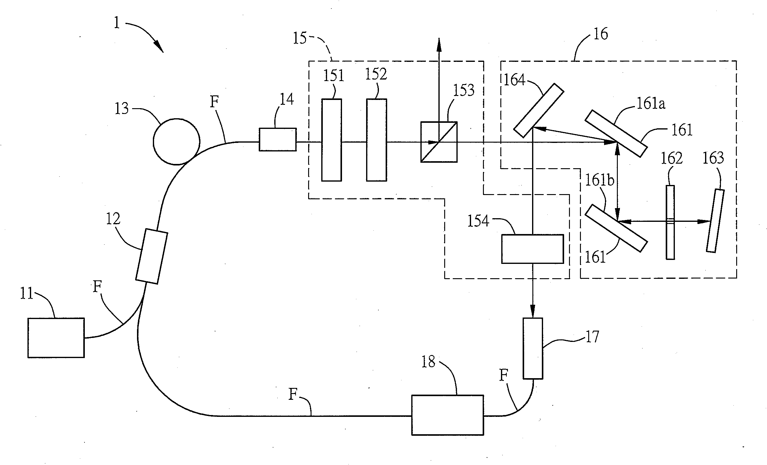
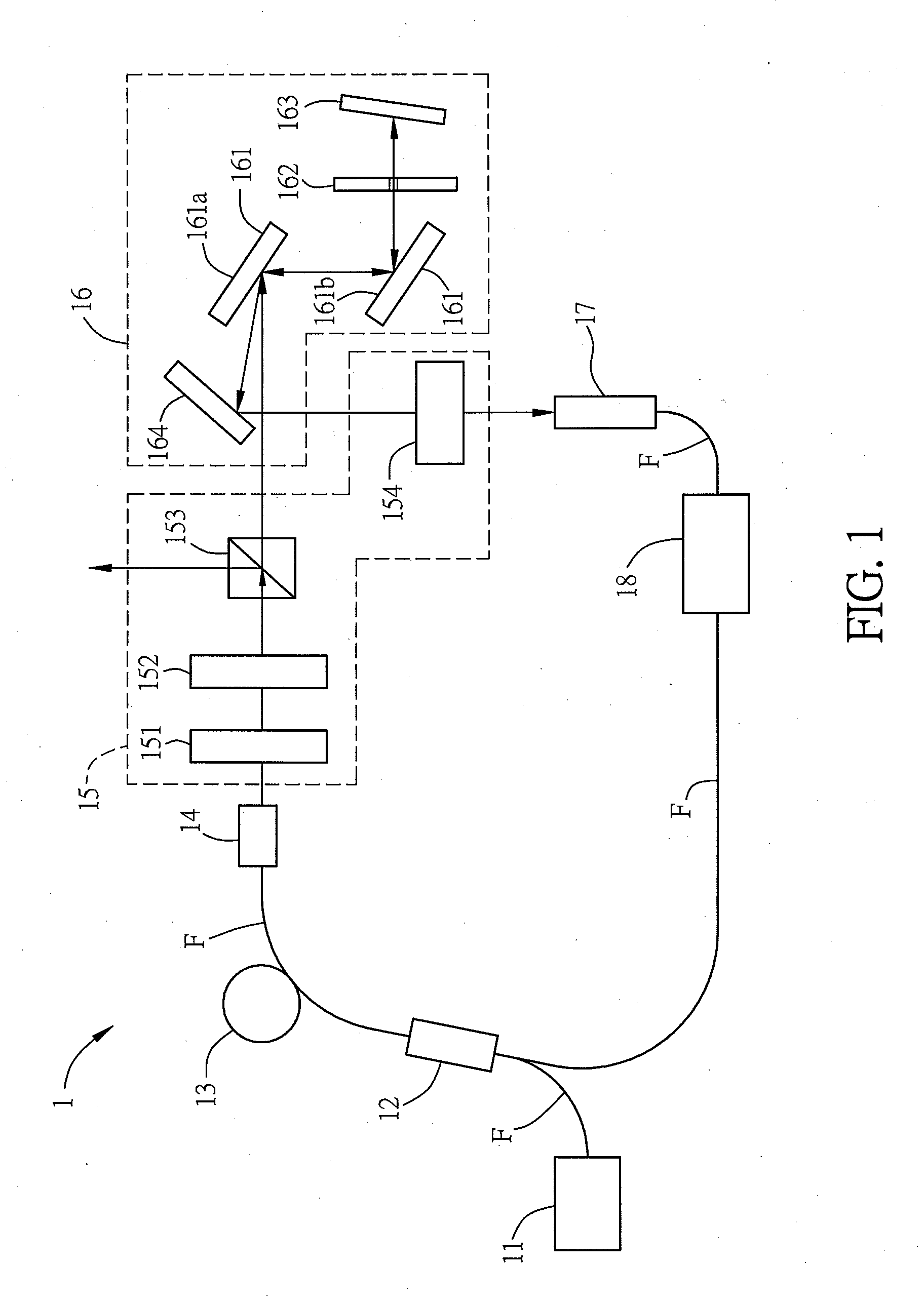
[0032]FIG. 1 is a schematic diagram of a fiber laser according to a preferred embodiment of the invention. As shown in FIG. 1, the fiber laser 1 is designed according to a mode-locked laser ring cavity, and thus can create Gaussian pulse or noise-like pulse with a narrowband or broadband. Therefore, it can be applied to the fields of optical detection (such as optical coherence tomography, OCT), radar system, signal communication, laser cutting, etc. The fiber laser 1 includes a pump light source 11, a passive optical fiber F, a power combiner unit 12, an ytterbium (Yb)-doped optical fiber 13, a first (optical) fiber alignment unit 14, a polarizing-splitting unit 15, a light modulation unit 16, a second fiber alignment unit 17 and a light separation unit 18.

[0033]The pump light source...


PUM


Abstract

A fiber laser having a ring resonance path comprises a pump light source, a Yb-doped optical fiber and a light modulation unit. The pump light source emits a pump light. The Yb-doped optical fiber is coupled with the pump light. The light modulation unit includes a grating pair, a diaphragm and two reflective elements. The grating pair is coupled with the pump light. The diaphragm includes an aperture. The light transmitted by the grating pair partially passes through the aperture and reaches one of the reflective elements to become a reflective light, and the reflective light passes through the aperture and is transmitted through the grating pair and the other reflective element to be coupled back with the ring resonance path.

Description

CROSS REFERENCE TO RELATED APPLICATIONS[0001]This Non-provisional application claims priority under 35 U.S.C. §119(a) on Patent Application No(s). 102117697 filed in Taiwan, Republic of China on May 20, 2013, the entire contents of which are hereby incorporated by reference.BACKGROUND OF THE INVENTION[0002]1. Field of Invention[0003]The invention relates to a fiber laser.[0004]2. Related Art[0005]Fiber laser, due to its advantages such as high stability, small size, portability and easy installation, plays an important role in the fields of optical communication, spectrum measurement and optical analysis. Besides, fiber laser has very high slope efficiency and optical power output, so it has become a widely applied laser system in industries.[0006]Ultrashort pulse laser (also referred to ultrafast laser) usually means the pulse laser with the pulse duration being of the order of a picosecond (10-12) or less. The widely applied ultrafast laser currently is the Ti:Sapphire mode-locked...

Claims


Application Information

Patent Timeline
Patent Type & Authority Applications(United States)
IPC IPC(8): H01S3/067
CPCH01S3/1106H01S3/06791H01S3/0675H01S3/0805H01S3/08054H01S3/094007H01S3/106H01S3/1112H01S3/1618H01S3/08086
Inventor PAN, CI-LINGZAYTSEV, ALEXEYLIN, CHIH-HSUANYOU, YI-JINGTSAI, FENG-HUAWANG, CHI-LUEN
Owner NATIONAL TSING HUA UNIVERSITY
Why Eureka
Try Eureka