System and apparatus for determining and controlling water clarity

a technology of water clarity and system, applied in the direction of instruments, separation processes, treatment involving filtration, etc., can solve the problems of equipment corrosion, unhealthy organic build-up or microbial life, and water quality problems, and achieve the effect of convenient and convenient fitting

Active Publication Date: 2014-11-27
KASTEN STEPHEN P
View PDF6 Cites 4 Cited by
  • Summary
  • Abstract
  • Description
  • Claims
  • Application Information

AI Technical Summary

Benefits of technology

[0012]In one exemplary embodiment of the invention, the invention is directed to an apparatus for determining and controlling water opacity or clarity that includes a water chamber having a water inlet, a water outlet, and a transparent member, a light source positioned near the transparent member for lighting the water contained in the water chamber, a light sensitive detection unit for detecting the light, and a control unit capable of receiving an output signal from the light sensitive detection unit for determining the opacity or clarity of the water contained within the water chamber. The control unit may also be capable of determining and sending a target signal to a water treatment system which functions to treat the water that flows through the water chamber.
[0013]In another exemplary embodiment of the apparatus of the present invention for determining and controlling water clarity or opacity, the apparatus includes a water chamber having opposing open ends and a water inlet and water outlet located between the opposing ends, a transparent lens covering each of the opposing open ends of the water chamber, a light source positioned at one opposing end of the water chamber, a light sensitive detection circuit positioned at the other opposing end of the water chamber, and a control unit capable of receiving an output signal from the light sensitive detection circuit and determining a target signal to send to a water treatment system which functions to treat water. The apparatus may also include an end cap placed over each transparent lens. The light sensitive detection circuit may include, but is not limited to, one or more of the following: a photoresistor, a photodiode, a phototransistor, and a photovoltaic cell. Further, the water chamber may comprise any number of shapes which facilitate building it into an existing pool or spa system including, but not limited to, a cylindrical shape that can be easily fitted between existing water lines and / or existing water filtration systems. In addition, the apparatus may include a local indicator connected to the control unit, and positioned close to a body of water that is capable of entering the water inlet of the water chamber, for indicating an opacity or clarity level of the water in the water chamber based on the output signal from the light sensitive detection circuit. The apparatus of the present invention may also include a remote indicator connected to the control unit, and positioned remotely from a body of water that is capable of entering the water inlet of the water chamber, for indicating an opacity or clarity level of the water in the water chamber based on the output signal from the light sensitive detection circuit. Further, such a remote indicator may be wirelessly connected to the control unit.
[0014]In still another exemplary embodiment, the present invention includes an apparatus for determining and controlling water clarity or opacity in a treatable body of water that includes a water chamber having opposing open ends, a water inlet for receiving water from a treatable body of water, and a water outlet for releasing water from the water chamber, the water inlet and outlet being positioned between opposing open ends of the water chamber, a transparent lens covering each of the opposing open ends of the water chamber, a light source positioned at one opposing end of the water chamber, a light sensitive detection circuit positioned at the other opposing end of the water chamber, and a control unit capable of both receiving an output signal from the light sensitive detection circuit and computing a target signal to send to a water treatment system which functions to treat the treatable body of water. The apparatus may also include an end cap placed over each transparent lens. The light sensitive detection circuit may include, but is not limited to, one or more of the following: a photoresistor, a photodiode, a phototransistor, and a photovoltaic cell. Further, the water chamber may comprise any number of shapes which facilitate building it into an existing pool or spa system including, but not limited to, a cylindrical shape that can be easily fitted between existing water lines and / or existing water filtration systems. In addition, the apparatus may include a local indicator connected to the control unit and positioned close to the treatable body of water for indicating an opacity or clarity level of the water in the water chamber based on the output signal from the light sensitive detection circuit. The apparatus of the present invention may also include a remote indicator connected to the control unit and positioned remotely from the treatable body of water for indicating an opacity or clarity level of the water in the water chamber based on the output signal from the light sensitive detection circuit. Further, such a remote indicator may be wirelessly connected to the control unit.
[0015]The present invention is also directed to a system for determining and controlling water opacity or clarity in a treatable body of water contained in a water containment apparatus which includes a body of water contained in the water containment apparatus, a light source capable of lighting up the water contained in the water containment apparatus, at least one transparent window positioned within the water containment apparatus, a light sensitive detection circuit positioned near said at least one transparent window, and a control unit capable of receiving an output signal from the light sensitive detection circuit for determining an opacity or clarity level of the body of water. The system may also include a local indicator connected to the control unit and positioned close to the body of water for indicating the clarity or opacity level of the body of water based on the output signal from the light sensitive detection circuit. In addition, the system may also include a remote indicator connected to the control unit and positioned remotely from the body of water for indicating the clarity or opacity level of the body of water based on the output signal from the light sensitive detection circuit. When the system includes a remote indicator, the remote indicator may be wirelessly connected to the control unit. The water containment apparatus may include, but is not limited to, a spa, a pool, a water trough, a water cistern, or a water tank. The system may further include a water treatment system connected to the body of water and the control unit where the control unit is also capable of computing and sending a target signal to the water treatment system to treat the body of water. The water treatment system may include, but is not limited to, any of the following: a bromine generator, a chlorine generator, a filtration device, and a chemical injection system. In addition, the control unit may be capable of repeatedly communicating with the water treatment system to maintain a predetermined level of an active disinfectant within the body of water where the predetermined level of the active disinfectant is determined based on the clarity level of the body of water. The water treatment system may include a chlorine generator with the control unit continually communicating with the chlorine generator to maintain a specific free chlorine level within the body of water where the specific level of free chlorine is determined based on the clarity level of the body of water.
[0016]The present invention is also directed to a method for determining and controlling water clarity in a spa and / or pool which includes the steps of a) providing a water chamber having at least one transparent window, a water inlet, and a water outlet, b) directing water from the spa and / or pool through the water chamber, c) employing a light source to light up water contained within the water chamber, d) providing a light sensitive detection circuit adjacent to the transparent window(s), and e) employing a control unit to receive an output signal from the light sensitive detection circuit to determine a clarity or opacity level of the water in the water chamber. The method may also include the step of f) utilizing the control unit to compute and send a signal to a water treatment system connected to the spa and / or pool to treat the water in the spa and / or pool. The method may further include continuously repeating steps b) through f) to maintain a predetermined level of an active disinfectant within the spa and / or pool where the predetermined level of the active disinfectant is determined based on the clarity or opacity level of the water in the water chamber. The water treatment system used in this method may be, but is not limited to, any of the following: a bromine generator, a chlorine generator, a filtration device, and a chemical injection system. If the method of the present invention is used for determining and controlling water clarity or opacity in a salt water pool and / or spa, the water treatment system may be a chlorine generator which functions to convert salt to chlorine through electrolysis with steps b) through f) being continuously being repeated to maintain a specific free chlorine level within the pool and / or spa. Finally, the method may also include the step of providing a local indicator positioned close to the pool and / or spa and / or a remote indicator positioned remotely from the pool and / or spa where the local and / or remote indicator is connected to the control unit for indicating the clarity level or opacity level of the water in the pool and / or spa.

Problems solved by technology

If the load is too high, the system will not generate enough sanitizer, resulting in under sanitation.
In these cases, unhealthy organic build up or microbial life may develop.
Alternatively, if the load is too light, extra chlorine or extra sanitizer may be generated resulting in irritation to bathers, equipment corrosion, and reduced generator cell life or reduced equipment life.
Over sanitation and under sanitation are particularly problematic in spa sanitizer systems, especially the newly developed spa sanitizer systems for salt water spas.
Unlike swimming pools, many spas sit idle for long periods of time.
In these cases, it is possible that a sanitizer or a chlorine / bromine generator (in the case of salt water spas) set for one type of use one week may produce far too much sanitizer the next week when the spa goes unused and remains covered.
The result can be severe corrosion of internal components and / or external decorative stainless jet trim, and severe deterioration of spa pillows, spa covers, and even jet seal O-rings.
From a practical standpoint, this has been historically difficult and expensive to implement on a consumer-level scale.

Method used


Image

  • System and apparatus for determining and controlling water clarity
  • System and apparatus for determining and controlling water clarity
  • System and apparatus for determining and controlling water clarity

Examples


Embodiment Construction

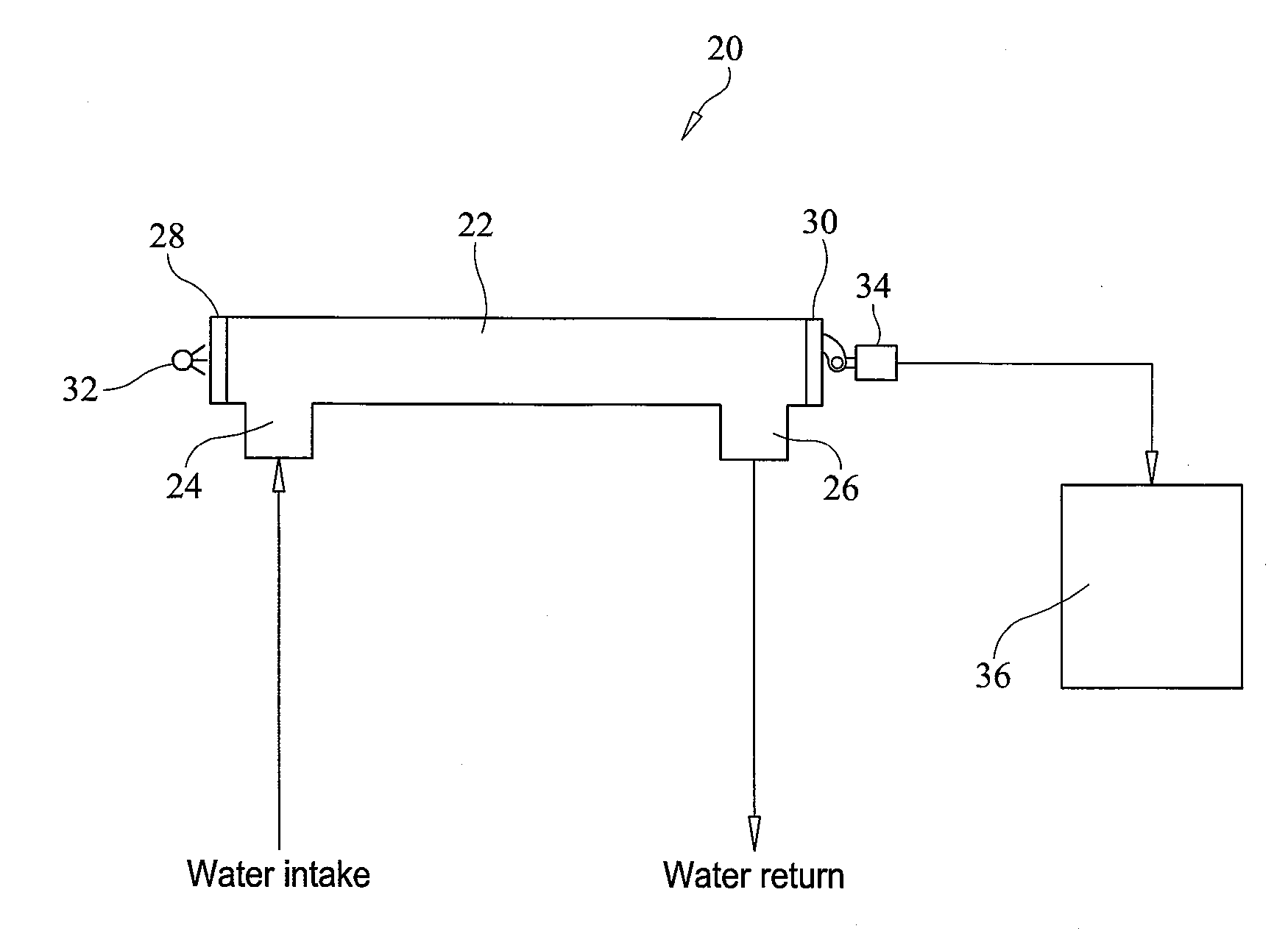
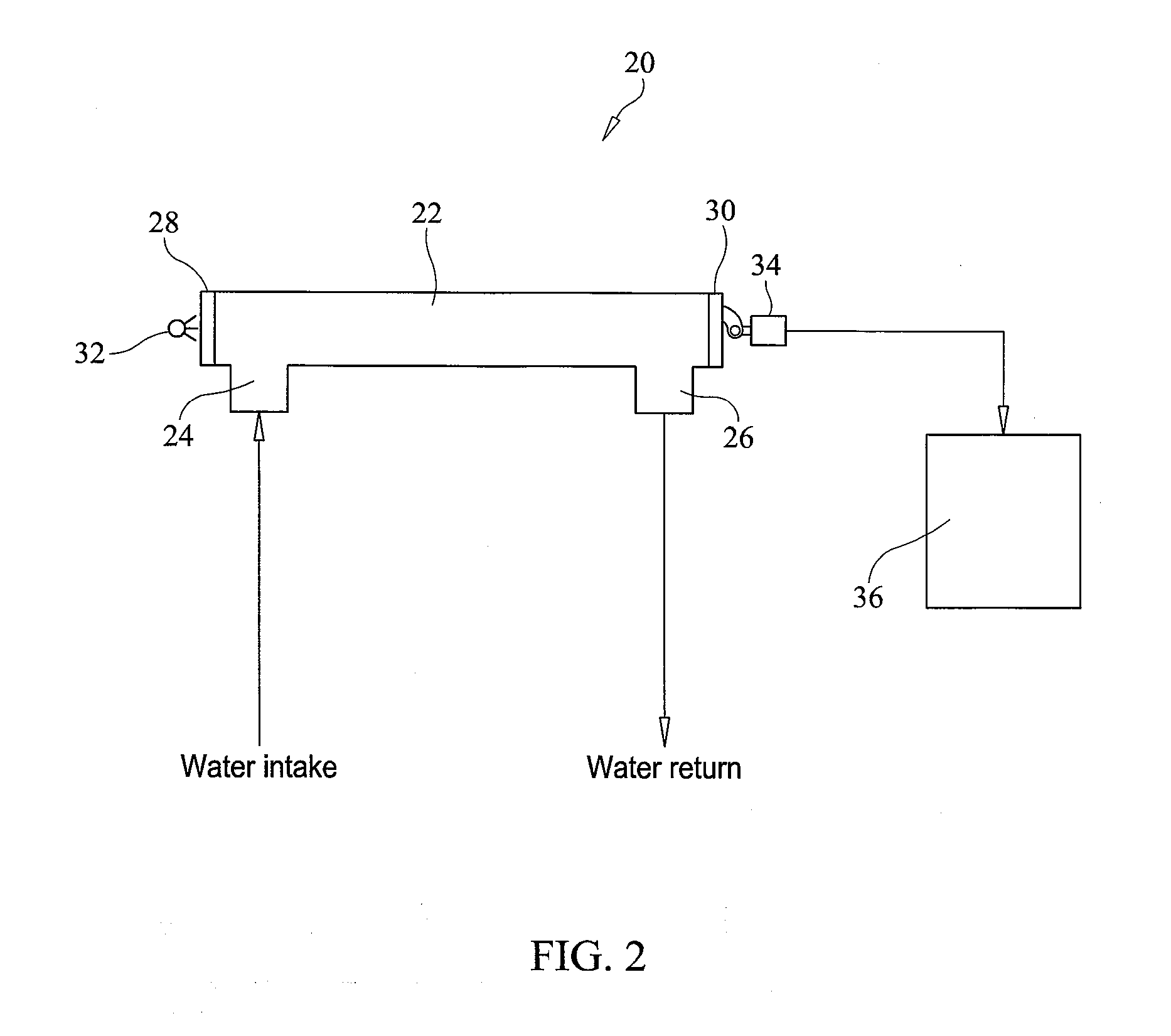
[0025]The present invention is directed to a system, method, and apparatus for determining, controlling and continuously monitoring the water clarity or water opacity of a treatable body of water such as the water contained in a spa, a pool, or any other body of water that needs to maintain a certain level of sanitation depending on its purpose. Any of the systems, methods, or apparatus that are described herein may be used to measure water clarity (i.e the clearness of the water) or water opacity (i.e. the opaqueness of the water). Either measurement of the water can be used to determine if the water needs more treatment, less treatment, or no treatment.

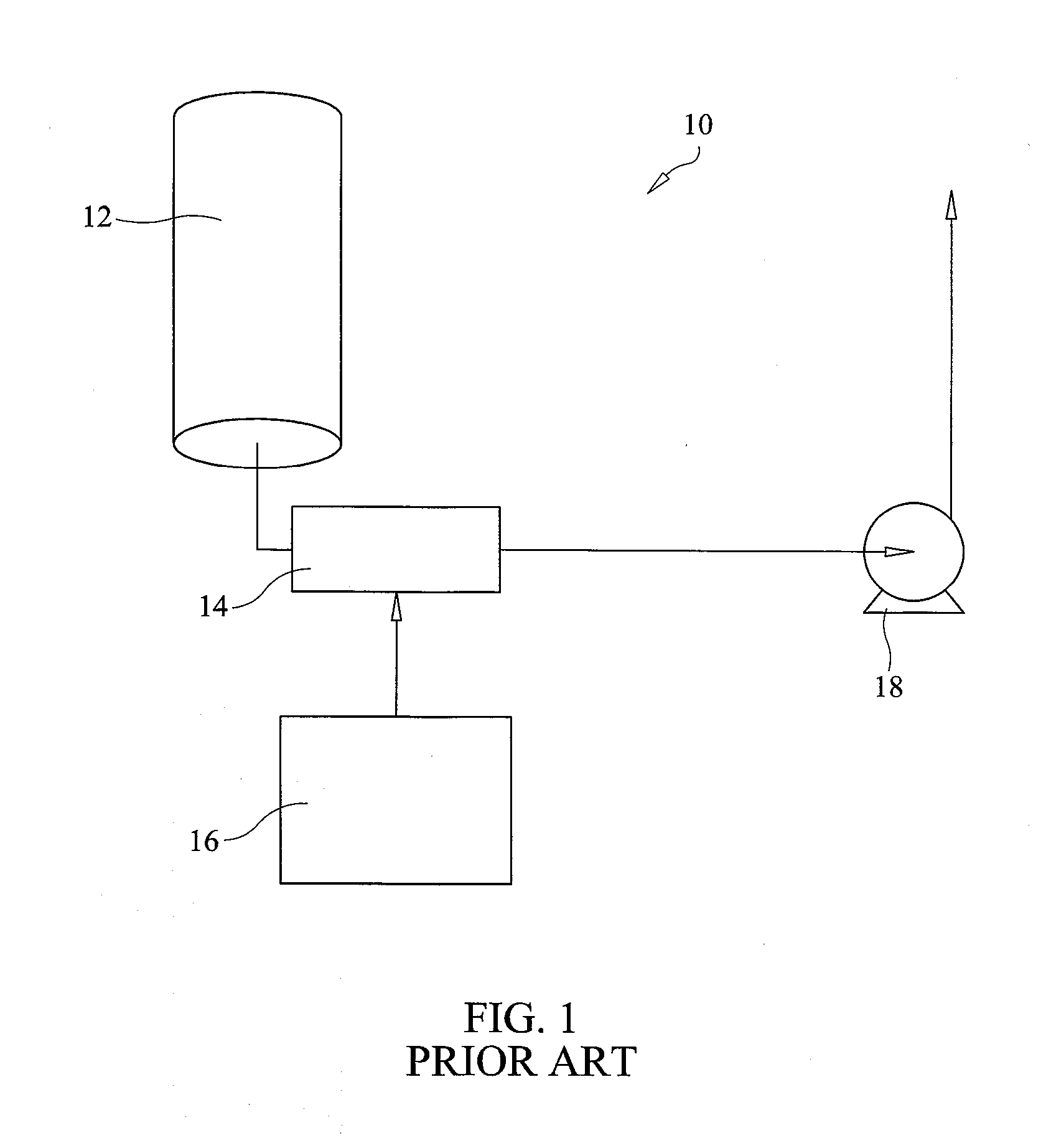
[0026]FIG. 1 is a schematic showing a prior art open loop chlorine generator control system used in salt water spas and / or a prior art open loop sanitation control system used in fresh water spas. In this open loop system 10, water from a spa (or pool) is drawn through a filter 12. Once the water passes through filter 12, it is dire...


PUM

PropertyMeasurementUnit
opacityaaaaaaaaaa
shapeaaaaaaaaaa
transparentaaaaaaaaaa

Abstract

A system, method and apparatus for determining and controlling water clarity or water opacity especially useful in pools, spas, and contained bodies of water.

Description

CROSS-REFERENCE TO RELATED APPLICATIONS[0001]This application claims priority to provisional patent application having Ser. No. 61 / 825,965, filed May 21, 2013, provisional patent application having Ser. No. 61 / 885,353, filed Oct. 1, 2013, and provisional patent application having Ser. No. 61 / 920,421, filed Dec. 23, 2013, which are all herein incorporated by reference in their entireties.FIELD OF INVENTION[0002]The present invention is directed to a system and apparatus for determining and controlling water clarity. More specifically, the present invention is directed to a system and apparatus for determining and controlling water clarity that includes a water chamber having an inlet, an outlet, and a transparent lens or window, a light source capable of lighting up the water contained in the water chamber, a light sensitive detection circuit positioned near the transparent lens or window of the water chamber, and a control unit capable of receiving an output signal from the light se...

Claims


Application Information

Patent Timeline
Patent Type & Authority Applications(United States)
IPC IPC(8): C02F1/00G21K5/08C02F1/76
CPCC02F1/008C02F1/763C02F1/766C02F2305/02C02F2103/42C02F2209/11C02F2303/04G21K5/08C02F1/004C02F1/32C02F1/76G05D21/02C02F2209/001C02F2209/006C02F2209/008
Inventor KASTEN, STEPHEN P.
Owner KASTEN STEPHEN P
Why Eureka
Try Eureka